


NAL Research Corporation (TN2012-02-V1.0)
7
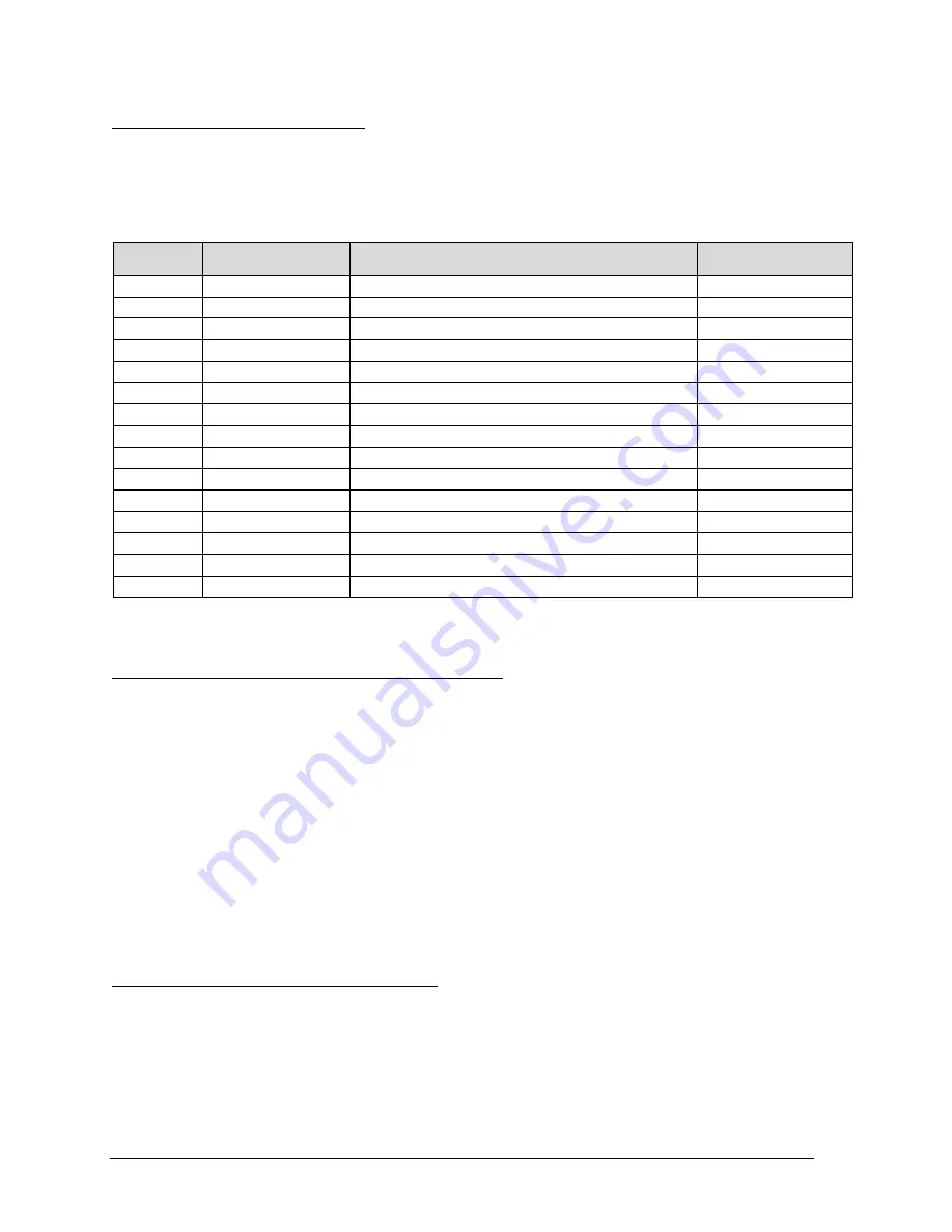
3.0 MULTI-INTERFACE CONNECTOR
The multi-interface connector is a male 15-pin miniature D-Sub type that includes four interfaces—
RS232, DC input power, ON/OFF control line, and TX_ACTIVE. The multi-interface connector pin
assignments are summarized in Table 1.
Table 1.
Pin assignment for the multi-interface connector.
3.1 RS232 Data Interface (Standard 9-Wire Configuration)
The A3LA-RS supports a standard RS232 data interface to a DTE incorporating hardware handshaking
and flow control. The RS232 data interface comprises of eight standard RS232 data, control and status
signals plus a ground level signal reference as shown in Table 1. This interface allows a connected DTE to
utilize the A3LA-RS’s modem functionality through standard AT and extended sets of AT commands. These
commands are defined in Appendix A. The A3LA-RS will automatically adjust to the DTE baud rate and
override the +IPR setting when dissimilar. Autobaud will occur on the following characters ‘a’, ‘A’ or CR
(carriage return). Autobaud will also occur on the escape sequence character, provided this is an odd
number of characters. Normally this is set to ‘+’ in register S2 (see Appendix A for details).
Note that the Ring Indicator is used by the A3LA-RS to indicate that a Mobile Terminated SBD (MT-SBD)
message is queued at the gateway. Application developers can monitor this pin and apply appropriate AT
commands to the A3LA-RS to retrieve the MT-SBD message.
3.2 RS232 Data Interface (3-Wire Configuration)
A 3-wire RS232 data interface may also be implemented. Because of risk of over-run and data loss
especially at high baud rates, the 9-wire interface is the recommended implementation. Several steps must
be taken to allow 3-wire configuration (i.e. only using S_TX, S_RX, and SIGNAL GND). These steps ensure
the A3LA-RS and DTE to work together without having hardware handshaking.
PIN #
SIGNAL
DESCRIPTION
INTERFACE
1
EXT_B+
External 3.5VDC – 6.0VDC input
DC Power
2
N/C
3
EXT_GND
External GND input
DC Power
4
EXT_ON_OFF
Power on/off control input
DC Power
5
N/C
6
S_TX
RS232 Transmit Data (Input)
RS232 Data
7
S_RX
RS232 Receive Data (Output)
RS232 Data
8
EXT_GND
External GND input
DC Power
9
DCD
RS232 Data Carrier Detect
RS232 Data
10
DSR
RS232 Data Set Ready
RS232 Data
11
CTS
RS232 Clear To Send
RS232 Data
12
RI
RS232 Ring Indicate
RS232 Data
13
RTS
RS232 Request To Send
RS232 Data
14
DTR
RS232 Data Terminal Ready
RS232 Data
15
TX_ACTIVE
Transmit Active Signal
GPIO