background image


3.


INSTALLATION ON THE HELMET 

Important

: Prior to installing the N-Com system, it is  recommended to write down the identification 

code affixed to the product (see chapter 18.5). 

 
You can download the installation video from 

www.n-com.it

 Download section. 


3.1.


Preliminary operations – Jet helmets or Flip-up helmets 


Open the helmet chin guard (only on Flip-up helmets). 


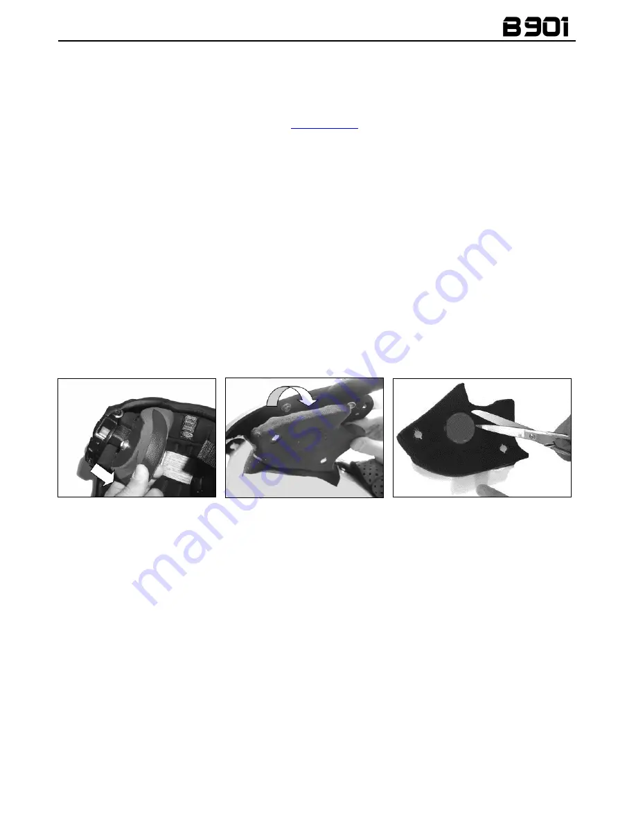
Pull out both comfort cheek pads, left and right, from the helmet. (Fig. 1)  


Remove  the  noise  reducers  from  the  cheek  pads  (if  present)  and  cut  the  insert  using  a  pair  of 
scissors, following the pre-cut dots. Reposition the noise reducers in the removable cheek pads. 


Take  out the rear section of the comfort padding,  pulling on the neck roll until it is released from 
the shell. Reposition the padding on the outside of the helmet for the time being.  


Unhook  the  press-stud  of  the  polystyrene  cheek  pads  by  pulling  toward  the  inside  of  the  helmet 
(Fig. 2), then remove the cheek pad by pulling it upward. 


Warning

:  in  case  the  polystyrene  cheek  pad  is  damaged  during  this  operation,  please  contact  your 

local dealer to replace it. 


Cut  out  the  round  foam  insert  that  covers  the  speaker  housing  from  the  polystyrene  cheek  pad 
using a pair of scissors, following the pre-cut dots. (Fig. 3). 


3.2.


Preliminary operations – Full-face helmets 


Remove  both comfort cheek pads, left and  right,  from the helmet (see  specific instructions in the 
helmet user manual). (Fig. 4) 


Open the visor. 


Remove  the  rear section  of the  comfort  padding,  pulling on  the neck  roll until it is released from 
the  shell  (see  specific  instructions  in  the  helmet  user  manual).Reposition  the  padding  on  the 
outside of the helmet for the time being. (Fig. 5) 


Remove the chin guard by pulling  on the special red tab (Fig. 6a), then remove the plug from the 
chin guard. (Fig. 6b)  


Gently remove the polystyrene cheek pads by pulling them upward. (Fig. 7) 

Warning

:  In  case  the  polystyrene  cheek  pad  is  damaged  during  this  operation,  please  contact  your 

local dealer to replace it. 


Fig. 1 


Fig. 2 


Fig. 3 

Summary of Contents for B901

Page 1: ...Com line are in compliance with standards as per the table below B901 The Bluetooth system complies with the main safety requirements and other applicable provisions of Directive 99 5 CE Directive 200...

Page 2: ......

Page 3: ...MOBILE PHONE 17 7 1 Speed dial 17 7 2 Conference call function 18 8 MANAGING TWO MOBILE PHONES OR BLUETOOTH DEVICES 19 9 MUSIC VIA BLUETOOTH 19 9 1 Sharing music via Bluetooth A2DP Sharing 19 10 MUSIC...

Page 4: ...disturbance or distraction while riding and at the same time allows you to distinctively hear background noises Do not operate your cell phone or other devices connected to N Com while riding your mot...

Page 5: ...of any accessory or of the battery charger always grab and pull the plug not the cable Do not use batteries for purposes other than the prescribed ones Never use batteries or battery chargers that tu...

Page 6: ...1 package contains e box Adesive Keypad Rechargeable battery Battery charger Mini USB jack wire Microphone Microphone foam Adhesive strips for cable Key Screw Microphone securing clip Microphone secur...

Page 7: ...f the helmet Fig 2 then remove the cheek pad by pulling it upward Warning in case the polystyrene cheek pad is damaged during this operation please contact your local dealer to replace it Cut out the...

Page 8: ...bric securing points Fig 8 Keep the foam used to cover the speakers housing in case you wish to use the helmet without the Bluetooth Kit system Fig 9 helmets X702GT X701 X603 Fig 10 helmet X702 In cas...

Page 9: ...Make sure that the fluorescent band is facing the inside of the helmet On certain helmets the housing for the microphone rod must be created by cutting out the helmet border gasket along the pre cut...

Page 10: ...Fig 17 Fig 18 Fig 19 Position the right hand side speaker in the specific cheek pad housing and secure it using the specific adhesive Fig 19 Reposition the right polystyrene cheek pad in its housing O...

Page 11: ...g 22 Secure the wiring underneath the plastic tab Close the cut parts using the cable fixing adhesives Fig 23 Fig 22 Fig 23 3 6 Positioning the e box Fig 24 Connect the microphone to the e box Fig 24...

Page 12: ...ke sure that the adhesive keyboard sticks properly Before you apply the keyboard make sure that the shell area is completely clean and grease or dirt free ONLY FOR JET HELMETS OR FLIP UP HELMETS Carry...

Page 13: ...akes up to 24 hours for the keyboard to stick completely During this time do not expose the helmet to atmospheric agents Hook up the flex cable of the adhesive keyboard to the e box Fig 34 Reposition...

Page 14: ...open and close the chin guard when the microphone is installed 3 8 Removing the system To remove the system from the helmet proceed as for the installation by removing the various parts Important to...

Page 15: ...ed off However if you adjust the volume during stand by mode it will affect volume levels of every audio source 4 2 Auto On Off function If the helmet does no move for more than 60 seconds the B901 sy...

Page 16: ...enabling the Audio boost Audio Boost all the audio sources inside the device will be reproduced at a higher and potentially less clear volume Press the ON confirmation key to enable disable the functi...

Page 17: ...Answering a phone call Briefly press any key when you hear the incoming call signal Vocal answer When you hear the ringtone say any word out loud Voice call Press ON and keep it pressed for about 2 s...

Page 18: ...Dial 3 Cancelled If you wish to exit the Speed Dial menu press the keys and until you hear the command Cancelled then press ON to confirm N B If no key is pressed within 15 seconds the system exits th...

Page 19: ...lay music Play Briefly press ON Pause function Pause When the player is connected and playing music briefly press ON Next track Skip When the player is playing music press for 2 about seconds Previous...

Page 20: ...from the navigator 12 FM RADIO Turning on the radio Press the ON key twice Turning off the radio Press the ON key twice New station automatic search Press and keep it pressed for 2 seconds Pre settin...

Page 21: ...13 2 Pairing up other N Com intercoms Important The procedure described here below refers exclusively to the pairing up of 900 series N Com systems with N Com systems OTHER THAN the 900 series 2 Make...

Page 22: ...restored If you do not want automatic reconnection press the ON key to stop the automatic reconnection attempts The B901 system is equipped with the VOX function which makes it possible to switch the...

Page 23: ...tart the conference communication between N Com intercom systems of the 900 series previously paired up and saved in the 3 available channels All systems must be turned on and available within the con...

Page 24: ...ed off 2 Put the system in the Configuration mode press the ON key and keep it pressed for 4 seconds until you hear the voice announcement Configuration 3 Press the pushbutton until you reach the opti...

Page 25: ...below 1 System A must have been paired up beforehand to two B systems Universal Intercom pair up and C 2 System A has to initiate the first intercom connection with system B Universal Intercom by pre...

Page 26: ...cting only 900 series N Com systems Note The Universal Conference mode can also be used by connecting 900 series N Com systems with other N Com devices B5 B1 4 etc 15 REMOTE CONTROL The B901 device ca...

Page 27: ...charger or to a USB outlet powered with the USB mini USB cable supplied as standard equipment The charge will take place as follows B901 system turned off When the B901 system is connected to the bat...

Page 28: ...X Hang up reject a phone call 2 sec Manual Device Connection 2 sec Phone Conference Activation CHANNEL 1 X Phone Conference Activation CHANNEL 2 x2 Phone Conference Activation CHANNEL 3 x3 Turning of...

Page 29: ...2 x2 Calling CHANNEL 3 x3 Group intercom connection 2 sec Group intercom disconnection X Radio Menu Turning on the Radio x2 Turning off the Radio x2 Automatic search for new station 2 sec Change stat...

Page 30: ...essories that are not part of the N Com product range Moreover the warranty does not cover product defects caused by fortuitous events modifications or adjustments causes of force majeur or damages de...

Page 31: ...with regenerated components with equivalent functions The replaced parts or components shall become property of Nolangroup THIS WARRANTY VOIDS AND REPLACES ANY OTHER WRITTEN OR VERBAL WARRANTIES PROVI...

Page 32: ...19 WARRANTY REGISTRATION FORM Product name B901 Identification code Buyer s Information Name Last name Address Phone e mail Dealer s stamp Date of purchase...

Reviews: