my!
WIND
Ltd.
Soola 1a
51013 Tartu, Estonia
Email: [email protected]
Website: www.mywind.ee
25 |
P a g e 2 6 / 0 7 / 2 0 1 9
Annex 1
– Levelling the tower with ITS-2-45 dual axis inclinometer
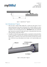
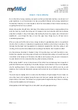
1. Place the dual axis inclinometer on top of the tower 2
nd
segment top and fix them together
with two M4 x 10 screws placed into the threaded holes in the 2
nd
segment top (see Figure
25).
! IMPORTANT:
Make sure that no small objects get caught between the sensor and the
2
nd
segment top. This will considerably alter the measurement results and turbine
performance.
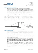
2. Take the wire coming from the sensor and fix it with cable ties to the generator wires coming
out from the hole for wires in the tower 1
st
segment (see Figure 4).
3. Perform
Step 7
of the
Erection of tower
chapter.
4. Unhook the lifting cable from the gin-pole to avoid any influence of side pressure.
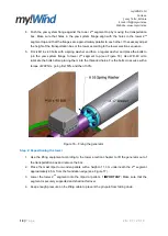
5. Take the dual axis inclinometer display and take the reading from the device. If the X and Y
axis readings on the display are more than +/- 0,5
˚ from the 0˚, perform next steps of this
Annex
.
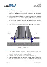
6. Adjust the tower vertical by turning the M27 nuts supporting the base plate up and down as
necessary (see Figure 14). Lower the bottom nuts away from the upper nuts before levelling
out the tower.
! IMPORTANT:
Do the adjustment incrementally, 1 nut turn at the time. Never
remove the upper M27 from the threaded bars, this could result in the tower falling down.
7. Stop the adjustment procedure once you have reached a vertical levelling of +/- 0,5
˚ for both
axes from the 0
˚ position.
! TIP:
After turning the nuts, wait for the measurement to stabilize,
before going forward.
8. Once the tower is vertically levelled, fix the M27 nuts cross wise with a torque of 1080 Nm,
going first 50% and then 100%.
9. Push the bottom counter nuts against the upper nuts and fix them with a torque of 540 Nm.
Figure 25
– Placing the inclinometer

