Temposonics
®
R-Series EtherNet/IP
TM
Operation Manual
I
24
I
5. Operation
5.1 Getting started
The sensor is factory-set to its order sizes and adjusted, i.e. the
required output signal corresponds exactly to the selected measuring
length.
Example: Output Ethernet/IP = 0…100 % stroke length
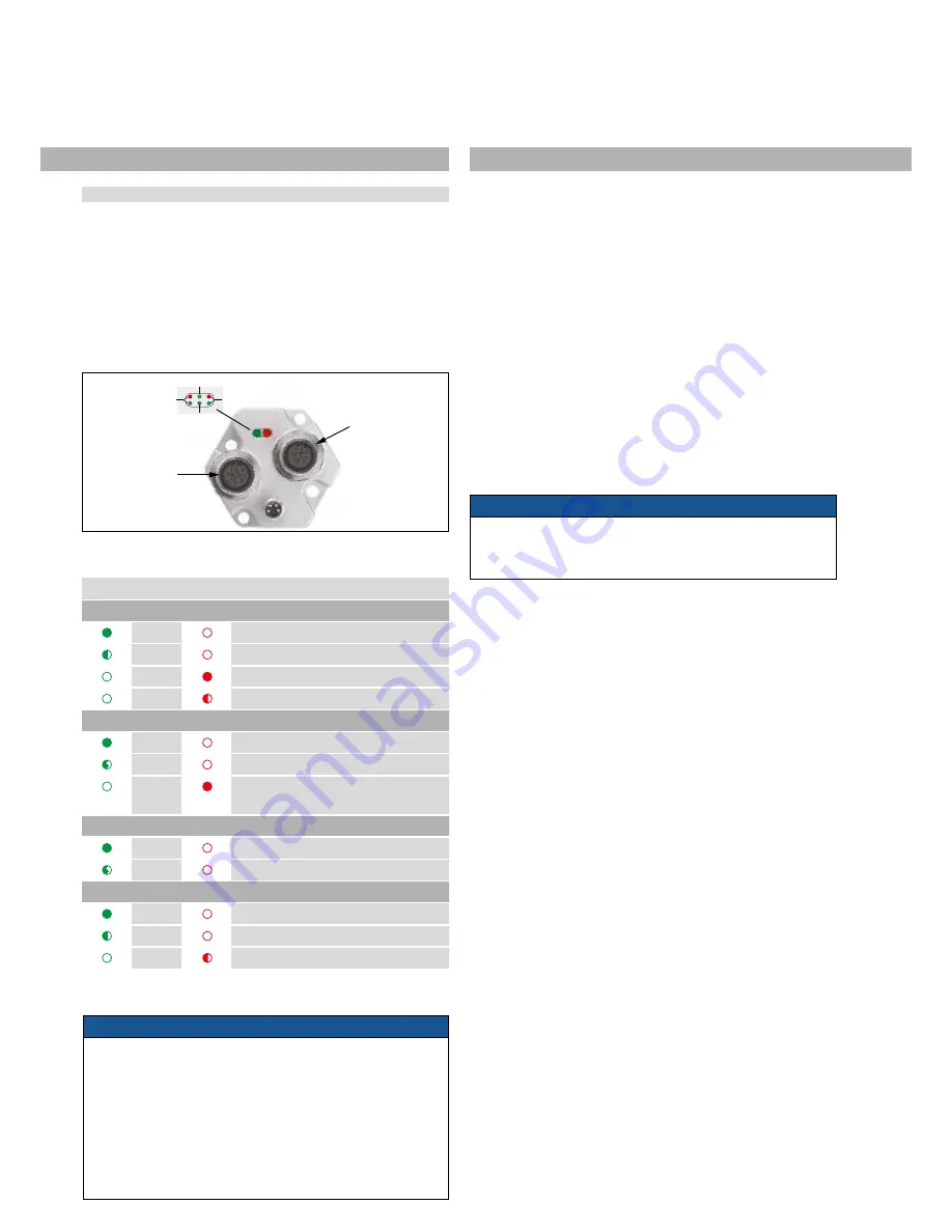
Diagnostic display
(Red/green) LEDs in the sensor electronics lid provide information
on the current sensor condition.
LED Status
Green
Red
Network Status
ON
OFF
Connection established
Flashing
OFF
No connection
OFF
ON
Unrecoverable error
OFF
Flashing Recoverable error
Port 1 (IN)
ON
OFF
LINK activity on port 1
Flickers
OFF
Data transfer on port 1
OFF
ON
No magnet /
Wrong quantity of magnets
Port 2 (OUT)
ON
OFF
LINK activity on port 2
Flickers
OFF
Data transfer on port 2
Module Status
ON
OFF
IP address configured
Flashing
OFF
IP address not configured
OFF
Flashing Duplicate of IP address recognized
Fig. 49: Location of the status LED
Fig. 48: Location of the status LED
NOTICE
1. Before initial switch-on, check carefully if the sensor has been
connected correctly.
2. Ensure that the sensor control system cannot be displaced in an
uncontrolled way when switching on.
3. If the sensor is operational and in operating mode after switching
on, the diagnostics LED is lit permanently (green).
4. Check the preset span start and end values of the measuring ran-
ge (see chapter 4) and correct them via the customer’s
control system, if necessary.
NOTICE
Physically connect the sensor to your network, but do not apply
power to the sensor. You will be instructed when it is time to power
the sensor.
6. IP Address Configuration
An example of configuring a MTS EtherNet/IP sensor will be shown
using an Allen-Bradley CompactLogix L35E controller, and the
RSLogix 5000 software from Rockwell. This example is written with
the understanding that the customer already has an EtherNet/IP
capable controller, and a working EtherNet/IP network.
The procedure to incorporate a MTS EtherNet/IP sensor into a network
is shown in the following 3 steps. Step 1 describes setting the IP
address of the sensor and step 2 installing the MTS EtherNet/IP EDS
file (download at www.mtssensors.com). To utilize the EDS file with
the add-on profile feature, the RSLogix 5000 software must be version
20 or later. By using the EDS add-on profile, the sensor parameters
and configuration data are loaded automatically to complete steps
3.1 and 3.2. If not installing the sensor EDS file, or if using an earlier
version of the RSLogix 5000 software, chapters 7.3 through 7.5
describe how to manually load the sensor parameter data. Also, if
needed later, the descriptions in step 3.2 can help when reviewing the
sensor parameter data and for making any changes.
In Port Traffic
Network
Status
Out Port Traffic
Module
Status
Port 1
Port 2


