


Temposonics
®
E-Series CANopen
Operation Manual
36
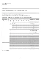
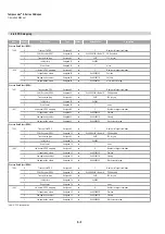
5.7 Process data
Transmission the data
The transmission type object (index 1800 ff subindex 2) enables to switch between the different transmission modes synchronous and
asynchronous mode.
5.7.1 Synchronous mode
When the CANopen sensor is in NMT operational state and the transmission type (Index 1800 ff subindex 2) is between n = 0…240 the
synchronous mode is enabled.
The PDO is transmitted by the CANopen sensor after receiving every nth sync object.
The sync object has the following format:
COB ID
Rx/Tx
DLC
DATA
D0
D1
D2
D3
D4
D5
D6
D7
0x080
Rx
0
–
–
–
–
–
–
–
Table 20: Sync object
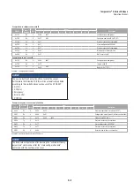
Table 21: Default PDO format
NOTICE
The COB ID of the sync object message can be programmed individually with index 1005.
So the COB ID of the sync message may be different, depending on the configuration of the sensor.
NOTICE
For the PDO message the measuring steps for the position (Pos) and velocity values can be read with object linear encoder
measuring step settings (Index 6005).
5.7.2 Asynchronous mode
When the CANopen sensor is in NMT operational state and the transmission type (Index 1800 ff subindex 2) is 254 or 255 the asynchronous
mode is enabled. The PDO is transmitted by the CANopen sensor after the event timer (Index 1800 ff subindex 5) is expired. The value of the
timer is given in ms.
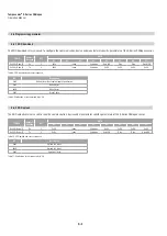
5.7.3 PDO message format
This is the format of the CAN sensor default PDO message. The current PDO mapping can be seen at Index 1A00 ff.
COB ID
Rx/Tx
DLC
DATA
D0
D1
D2
D3
D4
D5
D6
D7
0x180 + Node-ID
Tx
6
Pos LSB
Pos
Pos
Pos MSB
Velocity LSB
Velocity MSB
Status
–