


Temposonics
®
E-Series CANopen
Operation Manual
17
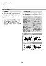
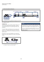
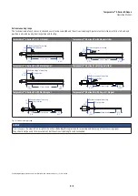
Controlling design dimensions are in millimeters and measurements in ( ) are in inches
4.6 Electrical connections
Placement of installation and cabling have vital influence on the sensor
EMC (electromagnetic compatibility). Hence correct installation of
this active electronic system and the EMC of the entire system must
be ensured by using suitable metal connectors, shielded cables
and grounding. Overvoltages or faulty connections can damage its
electronics despite protection against wrong polarity.
NOTICE
Never connect/disconnect the sensor when voltage is applied.
Instructions for connection
• Use low-resistance twisted pair and shielded cables and connect
the shield to ground externally via the controller equipment.
• Keep control and sign leads separate from power cables and
sufficiently far away from motor cables, frequency inverters,
valve lines, relays, etc.
• Use only connectors with metal housing and connect the shielding
to the connector housing.
• Keep the connection surface at both screening ends as large
as possible.
• Keep all non-shielded leads as short as possible.
• Keep the earth connection as short as possible with a large
cross section. Avoid ground loops.
• With potential differences between the ground connection of the
machine and the electronics, no compensating current flowing
over the shield is allowed. We recommend using an equipotential
bonding conductor with large cross-section or a cable with separate
dual shielding and connecting the shields only at one end.
• Use only stabilized power supplies and make sure that the specified
connecting values are met.
• Install potential compensating leads with large cross section, or use
cables with separate double shielding, and connect only one end of
the shield.
• Use only stabilized power supplies in compliance with the specified
connecting values.
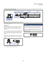
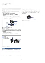
NOTICE
The E-Series EP and EL sensors must be grounded via grounding
lug on the sensor electronics housing (Fig. 5).
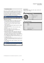
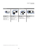
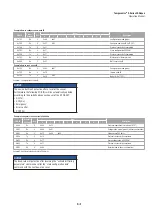
Connection types
Connect the sensor directly to the control system, indicator or other
evaluating systems as follows:
D34
M12 A-coded
Pin
Function
1
2
3
4
5
1
Shield
2
+24 VDC (−15 / +20 %)
3
DC Ground (0 V)
4
CAN_H
5
CAN_L
Cable outlet (EH model only)
Cable color Function
GY
CAN_L
PK
CAN_H
YE
–
GN
–
BN
+24 VDC (−15 / +20 %)
WH
DC Ground (0 V)