


Temposonics
®
E-Series CANopen
Operation Manual
20
CANopen bus interface
CANbus (Controller Area Network) is designed for high-speed data
exchange at machine level. CAN is a vendor independent open fieldbus
system, based on standard ISO 11898. CAN specifies the functional
and technical parameters with which the intelligent digital automation
devices can be networked via a master-slave serial link by using a
communication profile. Protocol architecture of functional and
applications data is oriented to the OSI reference model (ISO 7498).
Bus technology is administrated and developed by the user
organisation CiA (CAN in Automation).
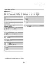
5.1 Encoder functionality system description
Temposonics
®
sensors are linear transducers and are suitable for a
CANopen protocol network. That is a CAN based higher layer protocol.
The sensor can be used as a CAN bus slave in networks with the
CANopen data protocol (CiA Standard DS 301 V4.02), the encoder
profile DS 406 V3.1 and the LSS Service DS 305 V2.1.1.
The sensor is performing Class C2 functionality.
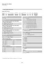
Network Management (NMT) – Slave
The NMT state machine defines the communication behavior of the
CANopen device.
Layer Setting Services (LSS) DS 305
Layer Setting Services (LSS) are used in order to configure the sensor
in terms of node ID and / or the baud rate. The sensor can be switched
to LSS configuration mode either globally or selectively.
Service Data Object (SDO)
SDO messages are used for reading and writing access to all entries
of the object dictionary. SDOs are used for device configuration in the
first place.
Identity objects
Identity including vendor ID, product code, revision number and
serial number.
Variable Process Data Object (PDO) mapping
The real-time data transfer of position, velocity and limit switch states
is performed by PDO messages. Data is transmitted within four
TPDO’s (transmit PDO) and each with a maximum 8 byte wide data
block. Variable PDO mapping can be configured via SDO messages.
Special Function Object (SFO) sync object
The sync object is broadcasted periodically by the synchronisation
device to all application devices. Synchronous PDOs will be
transmitted to the controller after receiving the sync message.
Emergency object
Emergency messages are triggered by the occurrence of a device
internal fatal error situation and are transmitted from the application
device concerned to the other devices with highest priority.
This makes them suitable for interrupting type error alerts.
Nodeguard object
The nodeguard object is used to monitor the whole network state.
The nodeguard object is sent cyclically to detect the sensor that the
controller works well. On a missing nodeguard object (i.e. controller
stopped) the sensor automaticly can stop PDO data transmission to
reduce the busload.
Heartbeat function
Instead of the node-guarding the heartbeat-function can be used.
The Producer-Heartbeat-Time defines the time frame in which
a new heartbeat message is sent.
Event timer
The event timer defines the asynchronous transmission period
for PDOs.
Encoder profile DS 406
Up to four work areas with upper and lower limits and corresponding
status register. Up to four cam switches with upper or lower threshold
level and status register
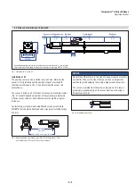
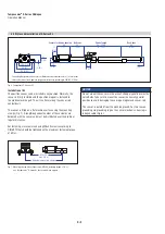
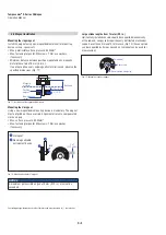
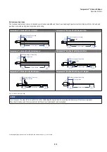
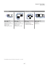
CANbus connection
The CANopen encoders are equipped with a bus trunk line in various
lengths and can be terminated in the device.
The devices do not have an integrated T-coupler nor they are looped
internally. If possible, drop lines should be avoided, as in principle they
lead to signal reflections. As a rule the reflections caused by the drop
lines are not critical, if they have completely decayed before the point
in time when the scanning occurs.
5. Operation