background image

English 

Operating Manual

14

Ensure that the cutting height 

adjustment lever is engaged 

correctly on the fixing pin.

If the cutting height adjustment 

lever is released when the cutter 

deck has been removed, the lever 

may shoot upwards uncontrollably 

due to the spring support.

Install the cutter wheels at the 

highest position.

Raise cutter deck into a position 

in which the V-belt is as 

horizontal as possible between 

the cutter deck and PTO clutch.

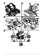
Remove the V belt (1) from the 

PTO clutch/motor pulley (2) – 

fig. 20. 

To do this, pull left or right side of 

the V-belt backwards and then 

downwards while manually 

turning the engine belt pulley in 

the opposite direction.

Note: Work carefully to avoid 

trapping your fingers.

Move cutting height adjustment 

lever to the lowest position  .

To disconnect the cutter deck 

from the hanger, pull the split 

pin (1) out of the left and right 

rear cutter deck hanger (2) – 

Fig. 21. In doing so, hold the 

cutter deck to prevent it from 

dropping on the ground.

Push cutter deck forwards to 

disconnect it from the front 

hanger (3) – Fig. 21.

Pull out the cutters from beneath 

the appliance.

Assembly

Warning 

If the cutting height adjustment 

lever is released when the cutter 

deck has been removed, the lever 

may shoot upwards uncontrollably 

due to the spring support.

To reinstall the cutters perform the 

above steps (for removing the 

cutters) in reverse order. Work 

proceeds faster when you are 

assisted by a second person. 

Note

Following assembly, check that the 

V-belt is positioned correctly and is 

not twisted – Fig. 22. 

Setting the cutter level

When mowing does not appear to 

be parallel to the lawn the cutters 

can be aligned.

Note

Before aligning the cutters check 

the tyre pressure on the appliance. 

Setting the side level

Fig. 14

Move the cutter deck to 

a medium height position.

Carefully turn the outer cutters 

(risk of injury) transverse to the 

drive direction.

Measure the distance between 

the ground and the ends of the 

two outer cutters. The result 

should be the same. 

If required, set the correct level 

on the setting segment (1) on the 

cutter deck side.

Lifting:

Loosen nut (2) anti-clockwise 

and turn nut (3) clockwise until 

the level is correct.

Retighten nut (2).

Lowering:

Turn nut (3) anti-clockwise until 

the level is correct.

Tighten nut (2) clockwise.

Set the level from front to back.

Fig. 15

Note

Set/check the side level before this 

adjustment.

Move the cutter deck to 

a medium height position.

Carefully turn the outer cutters 

(risk of injury) parallel to the drive 

direction.

Measure the distance between 

the ground and the end of the 

right cutter. The end of the front 

cutter should be about 3.2–6 mm 

lower than the end of the rear 

cutter. If required, adjust the front 

fixing bracket (1) equally.

Lifting:

Loosen both nuts (3) anti-

clockwise.

Turn both nuts (2) equally 

clockwise until the level is 

correct.

Retighten both nuts (3) 

clockwise.

Lowering:

Turn both nuts (2) equally anti-

clockwise until the level is 

correct.

Tighten both nuts (3) 

clockwise.

Off-season storage

Warning

Damage to mower materials

When the engine has cooled down, 

store the unit in a clean and dry 

room only. Always protect the 

mower against rust if it is to be left 

for comparatively long periods, 

e.g. over the winter.

At the end of the grass-cutting 

season or if the mower is not going 

to be used for longer than one 

month:

Clean the mower and the grass 

catcher.

Wipe all metal parts with an oily 

rag or spray them with oil to 

protect them from rust.

Charge battery with a battery 

charger.

When shutting down the unit for 

the winter, remove the battery, 

charge it and store in a dry/cool 

location (protected from frost). 

Charge the battery every 

4–6 weeks as well as before re-

installing it.

Drain the fuel tank (out in the 

open air only) and service the 

engine as described in the 

engine handbook.

Check tyre pressure. 

park the mower in a clean, dry 

room.

Warranty

The applicable warranty conditions 

in different countries are issued by 

our local subsidiary company or the 

importer of our products.

During the warranty period, any 

malfunctions of the unit caused by 

a material or manufacturing defect 

will be repaired free of charge. In 

the event of a warranty claim, 

please contact your original dealer 

or our nearest branch office.

Summary of Contents for Cub Cadet

Page 1: ...MTD Products Aktiengesellschaft Saarbrücken Germany E 15 FORM NO 769 10224A ...

Page 2: ......

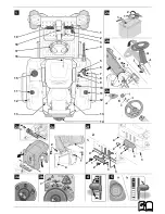
Page 3: ...16 17 18 15 11 12 13 19 4 5 6 7 8 9 10 11 12 13 14 3 2 1 1 4 3 1 1 1 2 1 2 3 3 4 2 2 1 1 2 3 3 4 2 2 1 1 2a 2b 2c 2d 2e 2f 3a 3b 4 5 ...

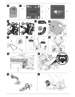
Page 4: ... 1 4 2 1 1 4 2 1 1 4 2 1 1 4 2 1 1 4 2 1 1 4 2 1 1 4 2 1 1 4 2 1 1 4 2 1 1 4 2 1 1 4 2 1 1 4 2 1 1 4 2 1 1 4 2 1 1 4 2 1 1 4 2 1 1 4 2 1 1 4 2 1 1 4 2 1 1 4 2 1 1 4 2 1 1 4 2 1 1 4 2 1 1 4 2 1 1 4 2 1 1 4 2 1 1 4 2 1 1 4 2 1 1 4 2 1 1 4 2 1 1 4 2 1 1 4 2 1 1 4 2 1 1 4 2 1 1 4 2 1 1 4 2 1 1 4 2 1 1 4 2 1 1 4 2 1 1 4 2 1 6 9 10 1 2 2 1 2 1 2 3 4 1 2 3 4 1 6 9 10 11 12 13 14 16 17 15 7 19 1 1 2 18 2 ...

Page 5: ...1 2 18 19 21 20 22 ...

Page 6: ...ions d origine Deutsch 30 Originalbetriebsanleitung Italiano 43 Istruzioni per l uso originali Svenska 57 Originalbruksanvisning Dansk 69 Originale driftsvejledning Norsk 81 Originale driftsanvisningen Suomi 93 Alkuperäinen käyttöohjekirja Eesti 106 Originaalkasutusjuhend ...

Page 7: ...has been provided and delivered by the manufacturer Keep this guide in a safe place where it is readily available whenever the machine is used If ownership of the mower changes hand this guide to the new owner Spare parts and accessories must satisfy the requirements specified by the manufacturer Therefore use original spare parts and original accessories only or spare parts and accessories author...

Page 8: ...nst possible injuries resulting from the cutting blade or objects that are propelled by it The unit may only be operated with the grass flap attached Safety interlock system The safety interlock system will only allow the engine to start when the driver is sitting on the seat the brake pedal has been depressed or the parking brake is in the park position the PTO switch is at the Off position The s...

Page 9: ... Risk of poisoning and injury from battery acid Wear safety goggles and protective gloves Do not allow battery acid to come into contact with skin If you get battery acid on your face or in your eyes wash off immedia tely with cold water and consult a doctor If you accidentally swallow battery acid drink plenty of water and consult a doctor immediately Store batteries out of the reach of children ...

Page 10: ...e 7 Combination indicator 8 PTO switch 9 Ignition lock 10 Fuel tap 11 Fuel tank 12 Tank contents display 13 Gear release lever 14 Trailer coupling 15 Can holder 16 Seat adjustment lever 17 Steering wheel 18 Pedal for parking brake cruise control 19 Brake pedal depending on model Forward pedal 1 Fig 12 The pedal controls the speed in a forward direction Reverse pedal 2 Fig 12 The pedal controls the...

Page 11: ...the air filter and outputs warning signals for oil level and battery voltage Changing the oil Every 50 operating hours oil change interval the letters CHG OIL SOON TIME appear in succession on the display for 7 minutes Change the engine oil immediately see engine operating manual Oil level If the letters LO OIL TIMEappear in succession on the display the engine oil level is too low Switch off the ...

Page 12: ... control Note The forwards and reverse accelerator pedal must not be used if the brake pedal is depressed This may damage the gears Operating procedure Follow the instructions in the engine handbook Danger Risk of injury No person especially children and or animals should be allowed to stand close to the mower while it is in use They could be injured by stones or similar objects that might be thro...

Page 13: ... is secure Check the oil level The oil level must be between the Full Max and Add Min marks see also engine handbook Check tyre pressure Check the tyre pressure see tyre walls on all wheels Correct if necessary Preparing for operation Park the appliance on a firm level surface and lock the parking brake Conduct all work with the engine switched off Remove the ignition key For all work on moving pa...

Page 14: ...he grass too low Drive in a straight line Never mow at high speed particularly when a mulching kit or grass catcher is installed Mulching Various appliances can also mulch when fitted with the corresponding accessories Ask your specialised dealer for details Note This appliance is designed to mow lawns Do not mow scrub weeds or overlong grass Switching off the machine Stopping the unit Release the...

Page 15: ...on firm level ground Lock the parking brake Cleaning the cutting mechanism Danger Injury hazard due to sharp cutting blades Wear protective gloves If the unit has more than one cutting mechanism moving one cutting mechanism may cause the other cutting mechanisms to move as well Caution when cleaning the cutters Warning Damage to engine The mower must not be tilted to an angle greater than 30 This ...

Page 16: ...hs during storage and before starting up the unit again Check the battery s charged state with a voltmeter When the charged state is less than 12 6 V DC recharge the battery max 12 V at 6 A with a battery charger in accordance with the table Note Follow the instructions in the operating manual for your battery charger Replacing fuses Replace defective fuses only with fuses of the same amperage Hyd...

Page 17: ...d set the correct level on the setting segment 1 on the cutter deck side Lifting Loosen nut 2 anti clockwise and turn nut 3 clockwise until the level is correct Retighten nut 2 Lowering Turn nut 3 anti clockwise until the level is correct Tighten nut 2 clockwise Set the level from front to back Fig 15 Note Set check the side level before this adjustment Move the cutter deck to a medium height posi...

Page 18: ...itch off PTO Battery not connected correctly Connect red cable to battery terminal and black cable to battery terminal Discharged or low battery Check the battery charge it or exchange it Fuse has tripped Replace fuse If the fuse trips repeatedly look for the cause usually short circuit Loose earth cable between engine and frame Connect earth cable Starter turns but engine does not start Choke and...

Reviews: