19
S
ection
4 — P
roduct
c
are
4.
Make the final connection on the engine
block of the tractor, away from the battery.
Attach to a unpainted part to assure a good
connection.
CAUTION
If the jumper battery is installed on a vehicle (i.e. car,
truck), do NOT start the vehicle’s engine when jump starting
your tractor.
5.
Start the tractor as instructed in the
Operation section of this manual.
6.
Set the tractor’s parking brake before
removing the jumper cables, in reverse
order of connection.
Charging
WARNING
Batteries give off an explosive gas while charging. Charge
the battery in a well ventilated area and keep away from an
open flame or pilot light as on a water heater, space heater,
furnace, clothes dryer or other gas appliances.
CAUTION
When charging your tractor’s battery, use only a charger
designed for 12V lead-acid batteries. Read your battery
charger’s Owner’s Manual prior to charging your tractor’s
battery. Always follow its instructions and heed its warnings.
If your tractor has not been put into use for an
extended period of time, charge the battery as
follows:
1.
For 30" deck models:
a.
Set your battery charger to deliver a
max of 10A.
b.
If your battery charger is automatic,
charge the battery until the charger
indicates that charging is complete. If
the charger is not automatic, charge for
no fewer than eight hours.
2.
For 24" deck models
a.
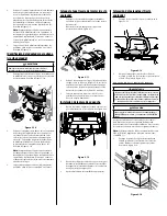
A separately available charging
unit is available for this tractor.
Instructions for using this feature
will accompany the battery charging
accessory. The charging unit will
plug in right next to the battery
as shown in Figure 4-13. To order
the battery charger, see the Parts/
Warranty supplement sheet.
Figure 4-13
Fuse
One 15A fuse is installed in your tractor’s wiring
harness located just above the battery, under
the left fender, to protect the tractor’s electrical
system from damage caused by excessive
amperage.
If the electrical system does not function, or your
tractor’s engine will not crank, first check to be
certain that the fuse has not blown. It can be found
at the rear of the riding mower, underneath the
fender located by the battery.
CAUTION
Always use a replacement fuse with the same amperage
capacity as the blown fuse.
Blade
WARNING
Shut the engine off and remove ignition key before removing
the cutting blade(s) for sharpening or replacement. Protect
your hands by using heavy gloves when grasping the blade.
WARNING
Periodically inspect the blade and/or spindle for cracks or
damage, especially after you’ve struck a foreign object. Do
not operate the machine until damaged components are
replaced.
CAUTION
If the cutting edge of the blade has previously been
sharpened, or if any metal separation is present, replace
the blades with new ones.
The blade may be removed as follows.
Note: It may be easier to change the blade
by first removing the deck from beneath
the tractor, (refer to Cutting Deck Removal
earlier in this section) then gently flip the
deck over to expose its underside. It is
possible to change the blade, however,
with the deck still attached to the tractor.
If attempting to change the blade with the
deck still installed on the tractor, first move
the deck lift lever to its highest cutting
position.
1.
Remove the mulch plug, deck chute or
bagging chute, if equipped, exposing the
deck chute opening.
2.
Using a block of wood or 2 x 4, insert it into
the deck opening and rotate the blade
around until it wedges the wood between
the deck opening and the cutting blade, as
shown in Figure 4-14.
Figure 4-14
3.
Remove the hex flange nut that secures the
blade to the spindle assembly. See the Inset
of Figure 4-14.
Note: The deck spindle has a normal
thread. To loosen, rotate the flange lock nut
counter-clockwise.
4.
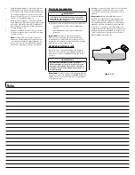
To properly sharpen the cutting blades,
remove equal amounts of metal from both
ends of the blades along the cutting edges,
parallel to the trailing edge, at a 25°- to 30°
angle. Always grind each cutting blade edge
equally to maintain proper blade balance.
See Figure 4-15.
Figure 4-15
WARNING
A poorly balanced blade will cause excessive vibration, may
damage the tractor and/or result in personal injury.
5.
Test the blade’s balance using a blade
balancer. Grind metal from the heavy side
until it balances evenly.
Note: When replacing the blade, be sure to
install the blade with the side of the blade
marked ‘‘Bottom’’ (or with a part number
stamped in it) facing the ground when the
mower is in the operating position.
CAUTION
Use a torque wrench to tighten the blade spindle hex flange
nut to between 70 ft-lbs and 90 ft-lbs.
Changing the Transmission Drive Belt
Note: Several components must be removed and
special tools (i.e. air/impact wrench) in order to
change the tractor’s drive belt. See an authorized
service dealer to have your drive belt replaced or
phone Customer Support to find a dealer near you.
See page 2 for details.
Summary of Contents for 769-11837A
Page 20: ...Notes 4 ...
Page 40: ...Notas 20 ...


