18
S
ection
4 — P
roduct
c
are
5.
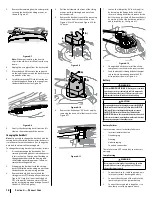
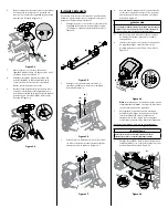
Remove the remaining bow-tie cotter pins (a)
securing the deck to the riding mower, as
shown in Figure 4-7.
(a)
(a)
Figure 4-7
Note: When reassembling, the bow-tie
clips (a) should be re-installed from the top
down.
6.
Unplug the wire pigtail from the deck switch.
7.
Move the deck lift lever into the top notch
on the right fender to raise the deck lift arms
up and out of the way.
8.
Carefully remove the PTO cable from the rear
of the cutting deck. Remove the spring from
the deck idler bracket. See Figure 4-8.
Figure 4-8
9.
Gently slide the cutting deck (from the left
side) out from underneath the tractor.
Changing the Deck Belt
Note: It is possible to change the deck belt with the
cutting deck still installed on the tractor; however it
is much easier to remove the deck first, change the
deck belt, then reinstall the cutting deck.
To change the cutting deck belt, proceed as follows:
1.
It is easiest to change the deck belt by first
removing the cutting deck as instructed earlier
in this section first. Skip this step if deciding to
change the deck belt with the mowing deck
still installed on the riding mower. Otherwise,
remove the cutting deck now.
2.
If changing the deck belt with the cutting
deck still installed on the riding mower, lower
the deck to the lowest mowing position.
3.
Remove the deck belt from around the
riding mower’s PTO drive pulley as shown in
Figure 4-6. Simply roll one side of the belt
OFF of the pulley and then work it OFF the
pulley by continuing around the pulley until
the belt is OFF of the pulley.
4.
Pull the belt towards the front of the riding
mower, pulling it through and out of the
belt keeper rod.
5.
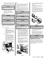
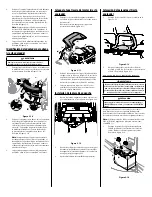
Remove the deck belt cover (a) by removing
the three hex bolts (b) that secure it. See
Figure 4-9 for 30" decks and Figure 4-10 for
24" decks.
(a)
(b)
(b)
(b)
Figure 4-9
(a)
(b)
(b)
(b)
Figure 4-10
6.
Remove the belt keeper (30" decks only) by
removing the hex bolt (a) that secures it. See
Figure 4-11.
(a)
Figure 4-11
7.
Loosen the idler pulley (24" decks only) (a)
by loosening the flange lock nut (b) that
secures it, enough to allow clearance for the
belt to move past it and off. Remove the belt
by working it off of the deck drive pulley (c)
and idler pulley (a). See Figure 4-12.
(c)
(a)
(b)
Figure 4-12
8.
Change the belt then reinstall the all the
components removed in the reverse order.
9.
Feed the deck belt through the belt keeper
rod and work it around and onto the PTO
drive pulley as shown in Figure 4-6.
Battery
WARNING
California
PROPOSITION 65:
Battery posts, terminals,
and related accessories contain lead and lead compounds,
chemicals known to the State of California to cause cancer
and reproductive harm. Wash hands after handling.
CAUTION
If removing the battery for cleaning, disconnect the NEGATIVE
(Black) wire from it’s terminal first, followed by the POSITIVE
(Red) wire. When re-installing the battery, always connect
the POSITIVE (Red) wire its terminal first, followed by the
NEGATIVE (Black) wire. Be certain that the wires are connected
to the correct terminals; reversing them could result in serious
damage to your engine’s alternating system.
Battery Failures
Some common causes for battery failure are:
•
Incorrect initial activation
•
Overcharging
•
Freezing
•
Undercharging
•
Corroded connections
These failures are NOT covered by your tractor’s
warranty.
Jump Starting
WARNING
Never jump start a damaged or frozen battery. Be certain
the vehicles do not touch, and ignitions are off. Do not
allow cable clamps to touch.
1.
Connect positive (
+
) cable to positive post
(
+
) of your tractor’s discharged battery.
2.
Connect the other end of the cable to the
(positive
+
) post of the jumper battery.
3.
Connect the second cable (negative
–
) to
the other post of the jumper battery.
Summary of Contents for 769-11837A
Page 20: ...Notes 4 ...
Page 40: ...Notas 20 ...


