background image

OPERATING AND MAINTENANCE MANUAL

Chapter 2 - Safety

TAEevo Tech MINI 02÷10

5

The data in this manual are not binding and they can be modified by the manufacturer without notice. 

Reproduction of this manual is strictly prohibited

EN

ENGLISH

C

HAPTER

2

S

AFETY

This unit is designed to ensure the best guarantees of safety and efficiency in its intended use, on the condition that it is 
installed, commissioned, and serviced in compliance with the instructions given in this manual.
The manual must therefore be studied by all those who want to install, use or maintain the unit.
The unit contains electrical components that operate at mains voltage and also moving parts.
All work on the unit must be carried out only after disconnecting the electrical supply. Maintenance operations involving 
work inside the unit must be performed by skilled and adequately qualified personnel equipped with suitable protection 
means (active and passive, e.g. work gloves) to ensure maximum safety.
Keep unauthorized persons (e.g. children) away from the place of installation of the unit.

2 . 1

G e n e r a l

When handling or maintaining the unit and all auxiliary equipment, personnel must operate with care observing all 
instructions concerning health and safety at the installation site.

ATTENTION


Numerous accidents that occur during operation and maintenance of the units are caused by failure to comply with

basic safety rules and precautions.

An accident can often be avoided by recognising a situation that is potentially hazardous.
The user must ensure that all personnel involved in operating and servicing the unit have read and understood all the 
warnings, precautions, prohibitions and notes given in this manual and affixed to the unit. Improper operation or maintenance 
of the unit and auxiliary equipment can be dangerous and can cause serious or fatal accidents.
We cannot anticipate every possible circumstance which might constitute a potential hazard.
The warnings in this manual are therefore not all-inclusive. 
If the user adopts operational procedures or uses tools or working procedures that are not specifically recommended, he must 
take care to ensure that the unit and the auxiliary equipment are not damaged or made unsafe and that no risks emerge in 
relation to persons or property. Any improper use of the unit will relieve the manufacturer from any liability for possible 
personal injury or property damage.
Arbitrary modifications made to the unit will automatically invalidate all forms of guarantee provided by the manufacturer.

ATTENTION


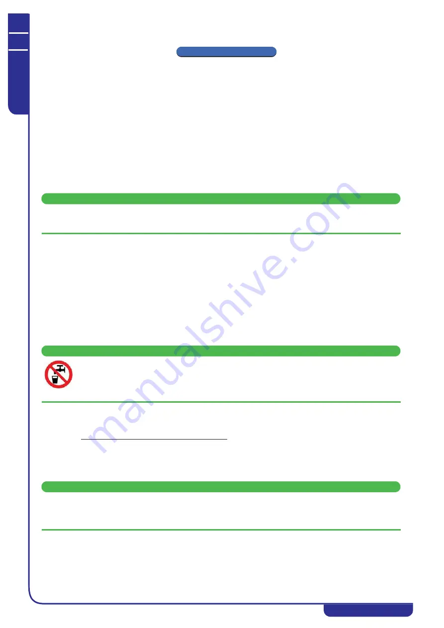
The hot / chilled water produced by units cannot be used for hygiene/sanitary or food applications. If it is

used for the above purposes, the installer must install an intermediate exchanger.
If the intermediate exchanger is not present, the installer must affix a warning notice to the effect “non potable
water”.

2 . 2

L i q u i d s   t o   b e   c o o l e d

The liquids to be cooled must be compatible with the materials used.
These can be water or mixtures of water and glycol, for example. In case of distilled or demineralised water, check the 
compatibility with materials.
It is advisable to work with pH between 7 and 8. If using chemical additives consult your supplier for more information 
concerning compatibility with materials in contact with the process fluid of the chiller.
The liquids to be cooled must not be flammable.

ATTENTION


If the liquids to be cooled contains dangerous substances (e.g. ethylene glycol) it is very important to collect any liquid

which leaks because it could cause damages to the ambient. Furthermore, when the chiller is no longer used, dangerous
liquids must be disposed of by firms specialised and authorised for treating them.

Summary of Contents for TAEevo Tech MINI

Page 1: ...T A E e v o T e c h M I N I WATER CHILLERS OPERATING AND MAINTENANCE MANUAL TAEevo Tech MINI 02 10 38178801054 Original instructions in Italian language...

Page 2: ...unit is on the display shows the regulator probe value If the unit is in standby mode the display shows 0 1 2 Switch on from digital input NOTE Refer to the wiring diagram for connection of the digit...

Page 3: ...operation 6 2 6 Disposal 7 2 7 Maintenance precautions 7 2 8 Refrigerant gases 8 2 8 1 Refrigerants safety datasheet 8 Chapter 3 TECHNICAL DATA 11 3 1 Declaration of conformity 12 3 2 Data for standar...

Page 4: ...from the keypad 22 7 3 2 Switch on from digital input 22 7 4 Setpoint 22 7 4 1 Displaying the setpoint 22 7 4 2 Modifying the setpoint 22 7 5 Maximum and minimum temperature 22 7 6 Modifying the value...

Page 5: ...ffixed to the unit and also in the dimensional drawings and refrigerant circuit diagrams The meaning of each symbol is indicated below 1 1 H o w t o i n t e r p r e t t h e m o d e l ATTENTION This ma...

Page 6: ...ntenance of the unit and auxiliary equipment can be dangerous and can cause serious or fatal accidents We cannot anticipate every possible circumstance which might constitute a potential hazard The wa...

Page 7: ...e unit empty and in the basic configuration The manufacturer does not supply load spreaders lifting straps or hooks with the unit NOTE Weight values are guideline with the water circuit empty The valu...

Page 8: ...carried out on the unit and the auxiliary equipment The frequency and the nature of the work required over a period can reveal adverse operating conditions that should be corrected ATTENTION Use only...

Page 9: ...heavily contaminated refrigerant system e g after a refrigerant compressor burnout a qualified refrigeration engineer must be consulted to carry out the task The manufacturer s instructions and local...

Page 10: ...Local effects Concentrations substantially above 1000 ppm v v can cause narcotic effects Inhalation of products in decomposition can lead to respiratory difficulty pulmonary oedema Long term toxicity...

Page 11: ...ne measures Do not smoke PHYSICAL AND CHEMICAL PROPERTIES Colour Colourless Odour Faint Boiling point 52 8 C at atmospheric pressure Flash point Non flammable Relative density 1 08 kg l at 25 C Solubi...

Page 12: ...REFRIGERANT Refrigerant fluid in the unit REFRIGERANT QUANTITY Quantity of refrigerant fluid contained in the unit MAX REFRIG PRESS Refrigerant circuit design pressure MAX REFRIG TEMP Refrigerant circ...

Page 13: ...s final test f Directives and standards g Officer responsible for technical file h Technical supervisor personal data Model TAEevo Tech MINI 02 03 05 08 10 Tank capacity water volume litres 15 15 15...

Page 14: ...strictly prohibited EN ENGLISH Available head TAEevo Tech MINI 02 03 Available head TAEevo Tech MINI 05 10 NOTE The pump must never run dry 100 150 200 250 300 350 400 0 1 0 2 0 2 0 3 0 3 0 4 0 4 0 5...

Page 15: ...3 2 FT global Test conditions Noise levels refer to operation of the unit at full load in nominal conditions Sound pressure level in hemispherical irradiation conditions at a distance of 1 m 3 2 FT fr...

Page 16: ...5 Evaporator The evaporator is of the finned core type water flows in contact with the finned surface at velocities such as to ensure low pressure drops while the refrigerant flows through the tubes...

Page 17: ...d exclusively to protect the unit in the event of inappropriate closing of the shut off valves The manufacturer advises strongly against operation of the by pass for continuous cycles or lengthy perio...

Page 18: ...e room temperature 3 The ambient air must be clean avoid sea ambients brackish air and not contain flammable gas or corrosive solvents 4 The minimum and maximum working ambient temperature are specifi...

Page 19: ...quantity of antifreeze solution 5 4 L i m i t o p e r a t i n g c o n d i t i o n s 1 For temperatures below 5 C use antifreeze solutions see 5 3 Freeze protection 5 5 P l u m b i n g c o n n e c t i...

Page 20: ...tact in compliance with the prescriptions of IEC 364 by means of a residual current device the nominal trip current of which should normally be set to 0 03 A 3 Make sure the level of protection agains...

Page 21: ...ly voltage is correct 6 Turn the machine main switch ON TAEevo Tech MINI 08 10 7 The Electronic Control Unit switches on 8 The unit is ready to start If with the first start up there is a high ambient...

Page 22: ...nations LED MODE MEANING On C Flashing Parameter menu On Compressor running Flashing Minimum OFF time active Flashing Alarm active On Pump running Key Function Displays or modifies held down for 3 the...

Page 23: ...e unit by closing the digital input contact the unit switches on it switches to standby OFF if it is opened The off command from keypad or digital input always overrides the on command If the unit is...

Page 24: ...sh 4 Edit it with the and keys 5 Press to save the new value and move on to the next parameter To quit Press with a parameter displayed or wait 15s NOTE The new value is saved even if the user quits t...

Page 25: ...turns red to indicate its presence 7 1 1 P a r a m e t e r l i s t Every parameter has a corresponding access level U user level ATTENTION Changing the default parameters may prevent the unit from fun...

Page 26: ...r the compressor and people within the immediate vicinity It is of manual reset type It opens the power circuit of the compressor and of the fan see wiring diagram When the discharge pressure of the r...

Page 27: ...urn it off when there is no thermal load as it turns off automatically when the preset water temperature has been reached 9 2 M a i n t e n a n c e ATTENTION Before proceeding with the maintenance of...

Page 28: ...election of the unit Check that the ambient temperature is lower than the value used for selecting the unit Check that the environment is well ventilated Clean the water filter The water filter should...

Page 29: ...1 See A1 1 low evaporation pressure Get a technician to check for leaks and eliminate them Fill the plant B Probe BT1 faulty B1 Probe faulty or parameters out of range B1 1 Message P1 appears Check o...

Page 30: ...e A1 E6 1 Water outlet temperature too high refrigerant compressor stops Restore the thermal load to within the preset limits Press the reset button on the cap of the pressure switch F Compressor prot...

Page 31: ...d dAO K Low temperature alarm K1 The alarm delay is too short or the alarm threshold too low K1 1 LA low temperature alarm displayed See Ch 7 5 Maximum and minimum temperature Verify parameters ALL L...

Page 32: ...sk of high pressure fluid ejection from pipelines in cooling circuit due to design pressure values being exceeded Contatto di parti del corpo con gas frigorigeno o residui di tubazione del circuito fr...

Page 33: ...bstances handled used produced or offloaded from the machine and materials used to construct the machine fire or explosion Risk of fire or explosion Install the system in an environment fitted with ad...

Page 34: ...chine instability caused by vibrations Hazards on contact with operating fluids risk of pollution due to dispersion of fluids into the environment Strictly observe all manual instructions Chapter 2 Sa...

Page 35: ...f the manual 32 Hazards generated by absence of and or position of measures instruments influencing safety disconnection of power sources Contact with live parts contact with high pressure fluids or g...

Page 36: ......

Reviews: