background image

5.5 Settings Tab

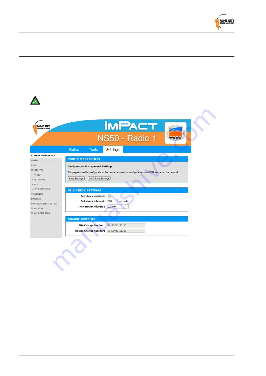
5.5.1 Managing Automatic TFTP Configuration

The

Config Management

screen is used to configure how the device retrieves its configuration from a

TFTP server on the network. For more information on TFTP, see

Centralised Configuration Management

on page 85.

Note:

These settings only affect TFTP configuration from a ICA v1.3.1 or earlier, and 3rd party

TFTP servers. If using AP Config Templates from ICA 1.4.0 or later, leave

Self check

disabled

(See

Device Management Overview

on page 86).

Self Check Settings

To enable automatic configuration from a TFTP server, tick the

Self check enabled

checkbox, enter the

desired

Self check interval

and

TFTP Server Address

, then click the

Save Settings

button.

Change Numbers

The two change numbers shown here are timestamps (formatted as YYYYMMDDhhmmss) showing the
last time the device's settings were updated via TFTP. The

Site Change Number

refers to general site

settings applied to all devices, whereas the

Device Change Number

refers to specific settings applied to

this device.

5.5.2 Configuring SNMP Settings

The

SNMP

screen contains Simple Network Management Protocol settings. SNMP is a protocol used by

the ICA and 3rd party SNMP browsers to monitor the status of compatible devices on the network. At
present, the ICA only uses this protocol to monitor for Port Up/Port Down errors on the NS50, and is not
affected by the settings below.

Revision C

66

NS50 User Guide

Configuration Using the Web Interface

Summary of Contents for Impact NS5001

Page 1: ...NS50 Wireless Network Switch User Guide Revision C NS50_UG_EN_C ...

Page 2: ......

Page 3: ...stallation 25 3 1 NS50 Mounting Options 26 3 2 Antenna Mounting Options 26 3 3 Installation Schemes 27 3 3 1 Installation in a Straight Drive 27 3 3 2 Installation in a Curved Decline Incline 28 3 3 3 Installation in a Stope 29 3 3 4 Installation at an Intersection 30 3 4 Connecting power to the NS50 31 3 5 Handling Composite Cable During Installation 32 3 6 Connecting Composite Cable to the NS50 ...

Page 4: ...e 61 5 4 3 Rebooting or Restoring the Network Device 63 5 4 4 Upgrading Firmware 63 5 5 Settings Tab 66 5 5 1 Managing Automatic TFTP Configuration 66 5 5 2 Configuring SNMP Settings 66 5 5 3 Setting Up the LAN 67 5 5 4 Configuring Wireless Radio 68 5 5 5 Configuring Wireless Networks 71 5 5 6 Configuring EAP Extensible Authentication Protocol 74 5 5 7 WDS Wireless Distribution System settings 76 ...

Page 5: ...ower Loss 95 Appendix C Ethernet Cable Specifications 97 Appendix D Device Discovery 99 Appendix E Time Zone Indices and Offsets 101 Appendix F Connecting a PC to an ImPact Network Device 105 Appendix G Maintenance Check list 109 Appendix H Acronyms 111 Appendix I ImPact NS50 Specifications 113 Appendix J Hardware Warranty 117 NS50 User Guide 5 Revision C ...

Page 6: ...Revision C 6 NS50 User Guide ...

Page 7: ...tralised Configuration Management C Copyright 2012 Mine Site Technologies Pty Ltd All rights reserved Mine Site Technologies Pty Ltd reserves the right to make changes to specifications and information in this manual without prior notice Mine Site Technologies Pty Ltd accepts no responsibility for any errors or omissions contained in this manual NS50 User Guide 7 Revision C ...

Page 8: ......

Page 9: ...tario P3E 5P5 CANADA Tel 1 705 675 7468 CHINA Hangzhou 4F Building 1 1413 Moganshan Road Hangzhou CHINA 310011 Tel 86 571 85803320x206 UNITED STATES Denver 13301 W 43rd Drive Golden Colorado 80403 USA Tel 1 303 951 0570 GERMANY Berlin Mine Site Technologies GmbH Uhlandstr 20 25 10623 Berlin GERMANY Tel 49 30 8861 4511 NS50 User Guide 9 Revision C ...

Page 10: ......

Page 11: ...nformation or references to the user Note The Important icon contains information to prevent damage to the product and injury to the user Important The Caution icon indicates to stop and pay attention or an action not to be performed Caution Related Publications ImPact Wireless Network Switch User Manual Additional Support For additional support please visit our website http www minesite com au No...

Page 12: ......

Page 13: ...ng safety and communications The NS50 has the following features Up to four fibre optic Gigabit Ethernet ports Four 10 100 Ethernet ports with Power over Ethernet PoE supply capability Up to two 802 11b g wireless access points Powder coated stainless steel enclosure sealed to comply with an Ingress Protection standard rating of IP65 AeroScout tag reading capability allowing real time tracking of ...

Page 14: ...ual is written for the NS5004 If you have one of the other models there may be slight differences Please note that these models have different internal hardware and it is not possible to upgrade one model into another Function Description Key Connector for data transmission and or DC power distribution Composite fibre power cable port 1 Labelling of the fibre optic ports Composite fibre port numbe...

Page 15: ...ctivity status LEDs 10 The top LED green flashes when data is transmitted or received and is solid when a link is established The lower LED orange indicates that PoE power is being supplied RP TNC jack for connecting an antenna to Radio 1 MAIN antenna port for Radio 1 11 RP TNC jack for connecting an antenna to Radio 1 AUX antenna port for Radio 1 12 A protective cover for the Ethernet port when i...

Page 16: ...rk This section describes a simple NS50 system layout in a mine The first NS50 in a network is connected to an Ethernet switch and power supply via a JB11 junction box See Connecting power to the NS50 on page 31 Units are typically connected in series down the mine tunnel by composite cable When the mine tunnel splits into different sections an additional NS50 is branched from the network NS50 or ...

Page 17: ...ion A fibre optic cable terminated to the fibre contacts of the NS50 composite connector Fibre only connection A composite cable providing fibre optic connectivity and power to the NS50 Fibre and DC power connection Fibre optic cabling provides numerous benefits over Ethernet cabling with superior signal integrity and no signal interference from high powered electronics It also enables units to be...

Page 18: ...If an SFP is changed the device must be rebooted or reset to detect the change 1 3 2 Ethernet Ports The NS50 has four external Ethernet ports that enable connection to other networking devices The four Ethernet ports also provide IEEE 802 3af PoE Power over Ethernet injector functionality allowing a single cable to be used for data and power to network devices Each Ethernet port s functionality ca...

Page 19: ...is also conducted to understand the behaviour of radio waves in the mine The following factors help determine network design Placement of Antennas Determining Distances between Wireless Network Switches Wireless coverage requirements of the mine Quantity and type of wireless client devices connected to the network Wired client devices connected to the network and their location Interconnection to ...

Page 20: ... NS50 needs to receive a minimum input of 15VDC to power PoE devices 48VDC power supplies are used for large networks to maximise the distance between power supplies For smaller networks of 1 2 nodes it is recommended that a lower voltage 24VDC power supply is used 2 3 Choosing Antennas Antennas are connected to each NS50 to provide wireless network coverage The type of wireless coverage surroundi...

Page 21: ... attached should be mounted in an elevated position within line of sight of mobile devices Ideally this would be situated high up on a tunnel ceiling or on the rock wall face The mounting location should be free from debris and avoid obstruction to vehicles equipment machinery vent tubing and cables NS50 units should not be installed in cut out areas such as safety bays and remuck bays due to sign...

Page 22: ...g signal paths The positioning of the antennas is crucial when AeroScout tags are used for asset tracking and location services AeroScout tags will not be read when there are antenna standing wave nulls Antennas need to be positioned to have best reception of tag messages For Antenna mounting options see Antenna Mounting Options on page 26 Revision C 22 NS50 User Guide Network System Design ...

Page 23: ...be installed closer together to provide sufficient coverage Distances between NS50 units will vary depending on the drift and tightness of the curve They are installed closer together on a tight curve Use the following steps to estimate the distance between NS50 units 1 Install one NS50 unit at the beginning of the curve 2 Install the second NS50 unit between 20 metres 65 feet to 40 metres 130 fee...

Page 24: ......

Page 25: ...power to the NS50 earth This ensures there is no current passing between grounds Handling Composite Cable During Installation of different potentials known as galvanic isolation Galvanic isolation must always be maintained with the NS50 ground Connecting Composite Cable to the NS50 terminals isolated from electrical earth and all antenna and antenna cable connections properly insulated Standard Co...

Page 26: ... in the table below Picture Description Mounting Option Mounting a Yagi antenna or panel antenna to the mine tunnel roof 1 The Yagi antenna is attached to the mounting pole using U clamps and nuts 2 A threaded metal bar is screwed into the mounting pole 3 A hole is drilled into the tunnel roof and the mounting pole is secured using chemset adhesive Mounting a Yagi antenna or panel antenna in a sto...

Page 27: ...llowing sections 3 3 1 Installation in a Straight Drive Two Yagi antennas are clamped to a mounting pole which is chemically adhered into the mine roof The antennas are positioned in opposite directions to provide long range wireless coverage Each antenna is connected to a separate WAC in the NS50 or a Wi Fi signal splitter can be used to split the signal from one WAC in two directions The network...

Page 28: ...ine roof A panel antenna is roof mounted in the middle of the curve providing wide wireless coverage Each antenna is connected to a WAC in the NS50 The network switch is cable tied to the rock mesh connected to the composite cable that provides power and network connectivity The network switch is also a link for power and network connectivity to devices in the next location Revision C 28 NS50 User...

Page 29: ... stope to provide wide wireless coverage A Yagi antenna is installed in the roof providing directional coverage down a straight drive Each antenna is connected to a WAC in the NS50 The network switch on a mounting plate is attached to a rock bolt The composite cable supplies power and network connectivity to the switch NS50 User Guide 29 Revision C Installation ...

Page 30: ...Yagi antenna is installed in the roof providing directional coverage down a straight drive Each antenna is connected to a WAC in the NS50 The network switch is cable tied to the rock mesh connected to the composite cable that provides power and network connectivity The network switch also acts as a link for power and network connectivity to devices in the next location Revision C 30 NS50 User Guid...

Page 31: ...ower up test of NS50 units is recommended To conduct a power up test 1 Connect the composite fibre power cable to a DC power source with correct termination Note that the DC supply must be between 10 and 50VDC NS50 User Guide 31 Revision C Installation ...

Page 32: ...onary measures should be noted during installation Never pull or create tension on the cable Unreel the cable from the cable reel or allow the weight of the cable to unreel as the vehicle is moving Do not bend the cable at sharp angles excessive bending can fracture or break the fibre optic cable Do not step on the cable 3 6 Connecting Composite Cable to the NS50 A composite cable is connected to ...

Page 33: ...bscrew on the retention arm 1 Slide out the retention arm from the NS50 2 Push down on the locking catch for the port and remove the cover 3 Align the pins on the connector to the composite fibre port 4 NS50 User Guide 33 Revision C Installation ...

Page 34: ...he retention arm back into the unit and screw the locking nut tight 7 Connecting a NS50 to a branch NS50 requires simply connecting composite cables to the additional fibre ports The connected fibre ports will cause the corresponding fibre port LEDs to become active If you are adding NS50 units to an existing system please consult your MST System Engineer to ensure power requirements are being met...

Page 35: ... of the NS50 and are used to connect to Ethernet devices such as computers Ethernet controlled PLCs hard wired Ethernet Phones and IP video devices An Ethernet cable with a RJ45 connector is used to connect PoE devices Ethernet cables are required to meet specifications for use in a mining environment in Ethernet Cable Specifications on page 97 The following procedure demonstrates how to connect a...

Page 36: ...t the wall ceiling 4 3 9 Connecting F LINK Terminated Composite Cable to the NS50 Connecting NS50 units to networks with existing WNS units requires a JB14 Junction Box supplied by MST to act as an adaptor between the existing F LINK terminated cable and the revised MST Composite connector The JB14 has four 10mm mounting holes and can be bolted to a flat surface or cable tied to the mesh in a tunn...

Page 37: ...cable port and remove the cover 1 Align the pins on the connector to the composite port 2 Insert the cable into the composite port and push the locking catch to the connector 3 Remove the protective cover from the F LINK cable port 4 NS50 User Guide 37 Revision C Installation ...

Page 38: ...s can be connected directly to the coaxial RP TNC jacks on the unit or mounted remotely by using coaxial cables Coaxial cable length should be kept as short as possible ideally less than 10m to minimise signal loss Important All cable and antenna connections must be electrically insulated using self amalgamating rubber tape The following procedure describes how to connect a coaxial cable to the NS...

Page 39: ... NS50 and tighten the outer sleeve 2 Insulate the connection using self amalgamating rubber tape Start at the base of the connection and pull back the rubber tape backing 3 Pull the tape tightly and tape around the connector at an angle until it is 25mm past the end of the connection 4 NS50 User Guide 39 Revision C Installation ...

Page 40: ...d antenna ports remain covered with the supplied dust caps Check there are no obstructions near the antennas that could hinder the radiation pattern 3 11 Manual Reset and Reboot The NS50 can be manually power cycled or reset to factory default settings as described below Picture Description Step Locate and identify the Reset button and the Factory Default buttons for CPU 1 and CPU 2 1 Revision C 4...

Page 41: ... factory default settings whilst the unit is powered up press and hold both the Reset and CPU Default button Release the Reset button while continuing to hold the CPU Default button for another 5 seconds 3 Note This procedure must be performed on each CPU to reset it to factory default settings NS50 User Guide 41 Revision C Installation ...

Page 42: ......

Page 43: ...anding Trunk and Access Ports A VLAN is a collection of nodes grouped according to their function or application rather than their physical location They are grouped VLANs and Wireless Networks Native VLAN in order to separate and prioritise data within a network VLANs are created when multiple applications such as voice telemetry data and video are required in a mining network NS50 User Guide 43 ...

Page 44: ... are being transmitted Priority ID ranges from 0 7 where 7 is the highest priority When a network switch receives a tagged frame the tag is read to determine the VLAN it belongs to The tag is removed and distributed to devices connected on the same VLAN When the network switch receives multiple frames it will prioritise the distribution of frames based on the Priority ID in the VLAN ID tag For mor...

Page 45: ...etwork switch 1 receives multiple frames they are tagged and sent via trunk ports to Wireless network switch 2 6 Wireless network switch 2 receives the frames and prioritises distribution 4 1 3 Port Allocation Physical ports on the NS50 can be configured to be either a trunk port or access port using the web browser interface or editing site configuration files when Trivial File Transfer Protocol ...

Page 46: ...fies the tagged frame as belonging to the Data VLAN and removes the tag 4 The untagged frame is sent via the wireless network SSID Data to Laptop 2 4 3 Native VLAN Trunk ports on the wireless network switch also support a Native VLAN The Native VLAN is where untagged frames will be allocated On the network switch the native VLAN is always the Infrastructure VLAN This allows client devices such as ...

Page 47: ...o wireless network switch 2 via the Trunk ports between the network switch units 5 Wireless network switch 2 allocates the untagged frame to the Infrastructure VLAN 6 The management CPU of wireless network switch 2 is always an Access port on the Infrastructure VLAN and will receive the frame 7 Any frame leaving the Management CPU is placed on the Infrastructure VLAN 8 All frames on the Infrastruc...

Page 48: ......

Page 49: ...ave a built in web server that is accessible by a PC to configure settings A PC can access the web Configuration screen Status Tab browser interface by making a TCP IP connection to the device For Tools Tab more information see Connecting a PC to an ImPact Network Device on page 105 Settings Tab The IP address of the network device can be located and configured using the MST Device Scanner tool Fo...

Page 50: ...e IP address of a newly connected device use the MST Device Scanner Devices running firmware 2 24 0 or earlier may default to 192 168 1 90 To log in to the web browser interface 1 Launch your web browser and enter http WAC IP address in the address field 2 The login screen is displayed 3 In the LOGIN dialog box select Admin from the User Name drop down box and type the password in the Password fie...

Page 51: ...OLS Web screens to configure password access time settings restoring factory defaults and firmware upgrades SETTINGS Screens to manage device configuration SNMP networking and tracking settings 5 3 Status Tab 5 3 1 Obtaining Device Information The Device Info status screen displays system time firmware version LAN and wireless LAN summary information NS50 User Guide 51 Revision C Configuration Usi...

Page 52: ...t an error when obtaining WLAN status or require to refresh the web browser screen 5 3 2 Wireless Client Information The Wireless status screen displays current information about wireless clients connected to the access point Revision C 52 NS50 User Guide Configuration Using the Web Interface ...

Page 53: ...gnal strength of the client device as received by the access point Note The Wireless Client Device List groups the devices by the wireless SSID with which they are associated 5 3 3 Viewing System Logs The Logs screen displays the device logs It is possible to filter by the type of logged events and the event level NS50 User Guide 53 Revision C Configuration Using the Web Interface ...

Page 54: ...lear the list A confirmation message box is displayed 3 Click OK to continue 4 Click Save Log to save the log as a text file A log of the clear action is recorded Any changes made to the log characteristics are also recorded in the log 5 3 4 Viewing Network Traffic Statistics The Statistics status screen provides network traffic statistics for the WAC s LAN interface and each of the wireless SSIDs...

Page 55: ...cessor due to errors collisions or network switch resource limitation RX Packets Dropped The number of frames dropped while being received from the switch processor due to errors collisions or network switch resource limitation Collisions The number of frames dropped due to Ethernet collisions Errors The number of transmission failures that caused the loss of a packet WLAN STATISTICS SSID The ID o...

Page 56: ...ture inside the switch processor The voltage of the supply rail The voltage of the PoE rail This will read as 0 volts DC if PoE is disabled The vendor and part number for each of the SFP modules The link speed duplex and PoE power status for each switch port 5 3 6 Viewing Switch Traffic The Switch Traffic screen shows current traffic statistics for each network port Revision C 56 NS50 User Guide C...

Page 57: ...iewing Tracking Information The Tracking status screen displays the status of the tracking servers that are registered to the network device NS50 User Guide 57 Revision C Configuration Using the Web Interface ...

Page 58: ...orts The Tags status screen displays the last ten AeroScout tag reads when asset tracking and location services are enabled The following information is displayed Revision C 58 NS50 User Guide Configuration Using the Web Interface ...

Page 59: ...by viewing sequence number Received RF signal strength 5 4 Tools Tab 5 4 1 Configuring Administrator and User Settings The administrator and user login can be configured on the Admin configuration screen The device configuration can also be saved to or restored from a configuration file Passwords The administrator and user password are used to restrict access to the web browser management tool It ...

Page 60: ... Admin configuration screen allows network switch settings to be saved as a gws file Saved configuration files can be used to restore settings to the device To save network switch settings as a configuration file 1 Click Save Configuration A File Download dialog box is displayed 2 Click on Save Select a folder to save the configuration file and click Save To restore the configuration of a device 1...

Page 61: ...4 Click Reboot the Device and then OK to reboot or click Continue to return to the previous configuration screen Rebooting the device will end the current configuration session 5 4 2 Setting the Time The Time configuration screen is used to define regional time settings on the device NS50 User Guide 61 Revision C Configuration Using the Web Interface ...

Page 62: ...gs To enable Automatic Time Configuration tick the Enable NTP server checkbox and enter an NTP server address or select one from the dropdown menu Note If an NTP server is enabled any manual changes to the time will be overridden the next time the device synchronises with the server To keep a manually set time Enable NTP Server should be unchecked To Set the Date and Time Manually select the appro...

Page 63: ...re WAC 2 Complete steps 1 4 for for every WAC on the network that you are upgrading then move onto step 5 Firmware upgrades may reset the network device to default factory settings please refer to the firmware release notes to determine if this will occur It is STRONGLY recommended to install ICA 1 4 1 or greater at the site and use the central configuration management capability to re apply devic...

Page 64: ...quired parameters for the specific device Save the new settings Wait for the device s Managed status to change from PENDING to CURRENT Note As a template can be applied to multiple devices it is fixed to DHCP for networking to avoid address conflicts If static IP addresses are required these must be set in the individual devices overridden parameters It is recommended that a client device PC or la...

Page 65: ...k switch will reboot after 60 seconds 5 Check the device s IP address in the Device Scanner to ensure that it has been correctly updated See Device Discovery on page 99 This address must match the IP address entered in the AeroScout System Manager for tracking to work 6 Log back on to the device s web interface and check the STATUS LOGS screen for any errors that may need to be addressed NS50 User...

Page 66: ...Self check interval and TFTP Server Address then click the Save Settings button Change Numbers The two change numbers shown here are timestamps formatted as YYYYMMDDhhmmss showing the last time the device s settings were updated via TFTP The Site Change Number refers to general site settings applied to all devices whereas the Device Change Number refers to specific settings applied to this device ...

Page 67: ...vice Community String The group to which the device belongs Unless otherwise necessary this is usually left as public 5 5 3 Setting Up the LAN The LAN configuration screen is used to configure Local Area Network settings To edit LAN settings click in the selected field in the dialog box LAN settings are described in the table below NS50 User Guide 67 Revision C Configuration Using the Web Interfac...

Page 68: ...Gateway Settings are dependent on the site s DNS design The DNS server used by the WAC when looking up host names Primary DNS Settings are dependent on the site s DNS design The backup DNS server used by the WAC when looking up host names Secondary DNS Leave the field blank if you do not wish to add a domain name Local domain name for the network Local Domain Name If the device is left on DHCP onl...

Page 69: ...scription and recommended settings are shown below 3 Click Save Settings Recommended Settings Description Field Used to enable or disable the WAC s radio Enable Wireless Radio Select the correct region for the site location Limits available channels to those allowed by local regulations Region NS50 User Guide 69 Revision C Configuration Using the Web Interface ...

Page 70: ...the antenna to be used for the reception of wireless frames The options are Receive Antenna Diversity if antennas are fitted to both of the radio s ports Main The MAIN antenna will always be used for reception Aux The AUX antenna will always be used for reception Diversity Both antennas will always be used for reception and the received frame with the best signal strength will be used Important En...

Page 71: ...termines what size data packet the low level RF protocol issues to an RTS packet RTS threshold Default setting is 100ms The amount of time between beacon transmissions Beacon Period The recommended DTIM interval is 1 A DTIM is a countdown informing clients of the next window for listening to broadcast and multicast messages Wireless clients detect the beacons and DTIM interval awaken on the DTIM i...

Page 72: ...t devices within range Visibility Status Keep Enabled unless multicast traffic is adversely affecting network performance Retransmit Multicast Enabled The access point will retransmit any multicast received from a wireless client back out to all wireless clients Disabled The access point will only forward wirelessly received multicast packets out the wired interface This can significantly improve ...

Page 73: ...encrypted mode will display configuration options WEP is the original wireless encryption standard This is rarely used WPA Personal provides a higher level of security and does not use a centralised authentication server WPA Enterprise as per WPA Personal but a RADIUS authentication server is used Note After a unit is reset to factory defaults it will have a single wireless network on channel 6 wi...

Page 74: ...y number that will be used 4 Select the Default WEP Key from the drop down box 5 Select Authentication from the drop down box By default it is set to Open which is more secure than Shared 5 5 6 Configuring EAP Extensible Authentication Protocol The Wireless EAP configuration screen is used to configure wireless authentication by a RADIUS server as used by WPA Enterprise Revision C 74 NS50 User Gui...

Page 75: ...ort number is 1812 Port number used by the access point to connect to the authentication server RADIUS server Port Password that matches with the authentication server Password used by the access point to access the RADIUS server RADIUS server Shared Secret If selected the user must always use the same device when Access to the RADIUS server by confirmation of the client device s MAC address MAC A...

Page 76: ...dress of each network device that the device will use WDS to connect to the network 5 Click Save Settings Note WDS links always operate as trunk ports with all VLANs passing across the trunk 5 5 8 Configuring Asset Tracking and Location Based Services The Tracking configuration screen establishes where AeroScout tag reports are sent as shown below An ImPact network device can communicate with an A...

Page 77: ... These settings are used to control what location reports are sent to the Positioning Engine If a Wi Fi tag or mobile unit report is received with an RSSI below the relevant threshold it is not sent to the Positioning Engine whether it is an AeroScout Positioning Engine or MST Tracker Engine The default threshold is 95 dBm but this can be raised or lowered according to specific site conditions and...

Page 78: ... are used by the Tracker Engine to determine if the Access Point is up or down These options are enabled by default Indicates which devices will be tracked by this Access Point AeroScout Tags Enabled MST Wi Fi Tags Enabled Mobile Units Enabled Advanced Settings Drop non exciter tag reports If enabled the Access Point will only send tag reports when the tag is in an AeroScout Exciter field This set...

Page 79: ...s require Ports 5 thru 8 allow the speed and duplex to be controlled Speed Duplex Speed Duplex to be hard coded due to poor Auto negotiation implementations Enabling 48v Power Over Ethernet 48VDC PoE supply for ports 5 8 can be enabled by selecting the PoE Power Rail Enable check box If this setting has been changed but not saved the Reset PoE button will change it back to its saved setting If the...

Page 80: ...only deny listed machines 3 Click on check boxes to enable Filter Wireless Clients and or Filter Wired Clients 4 Under Add MAC Address click on the Enable check box 5 Enter the MAC address of client device in the MAC Address field Click Copy Your PC s MAC Address to add your own computer to the list 6 Enter Computer Name in the supplied field and click Save The MAC address will appear in the MAC A...

Page 81: ...simplify administration Priority Priority ranges from 0 7 7 being the highest priority that is assigned to frames on this VLAN Note The first VLAN Infrastructure cannot be disabled because the management CPU is always on this VLAN By default VLANs are pre defined with recommended IDs and priorities This is based on commonly used applications in mines Once the VLANs are defined they can be saved by...

Page 82: ...igns the VLAN s to each physical switch port and each wireless network Physical switch ports can be assigned as Trunk or Access ports Wireless networks always act as Access ports on the selected VLAN Revision C 82 NS50 User Guide Configuration Using the Web Interface ...

Page 83: ...itch processor but VLAN membership for some ports is configured on WAC 1 and others on WAC 2 All physical ports can be assigned to be either a trunk port or access port NS50 User Guide 83 Revision C Configuration Using the Web Interface ...

Page 84: ... can be selected For a trunk port multiple VLANS can be selected 3 Click Save Settings to save VLAN port map settings Note To configure the VLAN port map properly it is recommended to understand the principles of VLANs For more details on VLANs see Understanding VLANs on page 43 Revision C 84 NS50 User Guide Configuration Using the Web Interface ...

Page 85: ...e RECOMMENDED For networks with an ICA v1 4 0 or higher AP settings can be managed from the ICA Administration console A customisable Site Default template is included at installation and further templates can be copied from it and modified separately Additionally individual APs can have specific settings overridden via the Administration Console In this case the ICA will push configuration change...

Page 86: ...nistration Console with relevant settings Configuration Site Configuration Configuration AP Config Templates Devices Access Points 6 1 1 Site Configuration This editor contains the option to Set new Access Points as Managed If checked all newly discovered Access Points will be configured according to the Site Default template by the ICA If disabled new APs must either have their management setting...

Page 87: ...ate Details This section contains the details for each template System ID is an automatically assigned identifier used by the ICA Name A name or description for the template Edit Parameters Individual parameters can be selected and modified or ignored for each template by clicking this link to open the Parameters dialogue box See Edit Parameters section below Editing Parameters In the Parameters d...

Page 88: ...lick OK to close the dialog box The Managed status of all available parameters can be changed at once using the Manage All and Manage None checkboxes below the list 6 1 3 Access Point Access Points APs become visible to the ICA after the map containing them is first synchronised from AeroScout Once visible APs are automatically added to the List of Access Points Revision C 88 NS50 User Guide Centr...

Page 89: ...via the web interface that conflict with the selected template or overridden parameters see below those changes will be automatically reverted by the ICA Settings that are not defined in the template will be ignored Editing Overridden Parameters Individual parameters specified in a template can be modified for the selected AP To modify any parameters click Edit Overridden Parameters In the Paramet...

Page 90: ...made click OK to close the dialog box The override status of all available parameters can be changed at once using the Override All and Override None checkboxes below the list 6 2 TFTP Server Overview Note This configuration method is not commonly used For more information on TFTP server and configuration file requirements for ImPact access points please contact MST Centralised configuration manag...

Page 91: ...ngs SNMP Simple Network Management Protocol snmp At present the ICA only uses this protocol to monitor for Port Up Port Down errors on the NS50 and is not affected by these settings adjust only if required for 3rd party monitoring software Asset Tracking and Location Servers tracking Positioning Tracker engines settings This is where AeroScout tag and Wi Fi client device information is sent Config...

Page 92: ...terprise security mode wireless eap x A primary and secondary backup RADIUS server can be set up and configured The x in each parameter should be replaced with primary or secondary WDS Wireless Distribution System wireless radio 1 wds Allows ImPact network devices to connect wirelessly where a fibre or ethernet connection is not practical wireless radio 1 wds peer x Up to six peered devices can be...

Page 93: ... the power supply is supplying the correct voltage current for the NS50 Check there is sufficient power available if extending the NS50 infrastructure Verify the fibre link is connected and active The NS50 fibre connector is not connected The fibre activity light is not on There is a network access issue The wireless network cannot be Check that the NS50 is properly installed LAN connections are c...

Page 94: ...the correct TCP IP settings to communicate with the network a wireless capable PC Restart the computer and check the network settings Refer to Connecting a PC to an ImPact Network Device on page 105 If this is not resolved try changing the DHCP setting to Obtain an IP address automatically Check the NS50 default configuration against the configuration of other devices on the network Check the port...

Page 95: ... free finish Any signs of cracks chips or dirt will affect connectivity B 2 Measuring and Testing for Power Loss Measuring power and loss requires a Optical Time Domain Reflectometer OTDR with a suitable adapter matching the fibre optic connector being tested To measure power in fibre optic cable 1 Set the OTDR to dBm and set the wavelengths according to the fibre optic cable being tested 2 Attach...

Page 96: ...Power loss Component 0 5 dBi Connector 1 dBi km 1300nm Multi mode fibre 0 5 dBi km 1300nm 0 4 dBi km 1550nm Single mode fibre Revision C 96 NS50 User Guide Composite Cable Testing ...

Page 97: ...re cable for lengths greater than 30m Cable and Parts Description Order Code Description W NS50 RJ45 PLUG Bayonet back shell for RJ45 connector The choice of RJ45 crimp will depend on the type of wire used stranded or solid core Generic brand crimps may be used Note Both solid and stranded core RJ45 connectors at the network switch end require a bayonet back shell RJ45 to M12 Ethernet Cable Wiring...

Page 98: ......

Page 99: ...Address The MAC address of the device Interface The network interface via which the Device Scanner is communicating with the device ID The serial number on the device casing Firmware The version number of the firmware running on the device Status The uptime of the device This can be used to easily determine which devices have recently been connected to the network Revision The hardware revision of...

Page 100: ...Revision C 100 NS50 User Guide Device Discovery ...

Page 101: ... 5 25200 Arizona 6 25200 Mountain Time US Canada 7 21600 Central America 8 21600 Mexico City 9 21600 Saskatchewan 10 18000 Bogota Lima Quito 11 18000 Eastern Time US Canada 12 18000 Indiana East 13 14400 Atlantic Time Canada 14 14400 Caracas La Paz 15 14400 Santiago 16 10800 Newfoundland 17 10800 Brazilia 18 10800 Buenos Aires Georgetown 19 10800 Greenland 20 7200 Mid Atlantic 21 3600 Azores 22 36...

Page 102: ...0 Baghdad 37 10800 Kuwait Riyadh 38 10800 Moscow St Petersburg Volgograd 39 10800 Nairobi 40 10800 Tehran 41 14400 Abu Dhabi Muscat 42 14400 Baku Tbilisi Yerevan 43 16200 Kabul 44 18000 Ekaterinburg 45 18000 Islamabad Karachi Tashkent 46 19800 Calcutta Chennai Mumbai New Delhi 47 20700 Kathmandu 48 21600 Almaty Novosibirsk 49 21600 Astana Dhaka 50 21600 Sri Jayawardenepura 51 23400 Rangoon 52 2520...

Page 103: ...400 Adelaide 63 32400 Darwin 64 36000 Brisbane 65 36000 Canberra Melbourne Sydney 66 36000 Guam Port Moresby 67 36000 Hobart 68 36000 Vladivostok 69 39600 Magadan Solomon Is New Caledonia 70 43200 Auckland Wellington 71 43200 Fiji Kamchatka Marshall Is 72 46800 Nuku alofa Tonga 73 NS50 User Guide 103 Revision C Time Zone Indices and Offsets ...

Page 104: ......

Page 105: ...eless Network Switch or WAP 1 Connect a PC to the device s Ethernet port with an Ethernet cable If the PC is already part of the network note its TCP IP configuration settings 2 Click Start Control Panel Open Network Connections 3 Right click Local Area Connection and select Properties The Local Area Connection Properties window will open NS50 User Guide 105 Revision C ...

Page 106: ...nternet Protocol TCP IP then click Properties The Internet Protocol TCP IP Properties dialog box is displayed 5 Click the Use the following IP address option button Revision C 106 NS50 User Guide Connecting a PC to an ImPact Network Device ...

Page 107: ...ixed static IP address within the Subnet range of the target device s IP address for example 192 168 1 100 7 In the Subnet mask field enter 255 255 255 0 Click OK NS50 User Guide 107 Revision C Connecting a PC to an ImPact Network Device ...

Page 108: ......

Page 109: ...ble for any damage to the insulation or connection Check the antennas directional alignment Check all Ethernet cable connections are secure Ethernet connections PoE Check dust covers are present and secure on unused Ethernet ports Check the junction box connection is secure Junction Box Check the power LED is lit green Display LEDs Check the status LED is blinking green at approximately 1 second i...

Page 110: ...Stand 50M away from the ImPact NS50 with two MST RFID tags 2 Open the NS50 web browser interface and select the STATUS TAGS web page 3 Verify that the two tags have been detected by the network switch and check the received signal strength is within specification Refer to commissioning data Open the front cover and check inside for water and dust Ingress Revision C 110 NS50 User Guide Maintenance ...

Page 111: ... Technologies MST Network Switch NS Power Over Ethernet PoE Power Supply Unit PSU Radio Frequency RF Service Set Identifier SSID Small Form factor Pluggable optical transceiver module SFP User Datagram Protocol UDP Virtual Local Area Network VLAN Wireless Access Card WAC Wireless Access Point WAP Wired Equivalent Privacy WEP Wireless Network Switch WNS Wi Fi Protected Access WPA NS50 User Guide 11...

Page 112: ......

Page 113: ...mperature 5 95 Operating Humidity Power 24 VDC nominal 8 54 VDC operating PoE requires a 15 54 VDC supply 15 may cause instability 54 may damage connected PoE devices Supply Voltage 60 VDC maximum input voltage 60 will damage the unit Replaceable slow blow thermal fuses on voltage arrestor transient suppression board Protection Power Consumption Maximum W Idle W PoE 48V rail Enabled PoE 48V rail D...

Page 114: ...dio ports IEEE 802 11b up to 11Mbps IEEE 802 11g up to 54Mbps Standards Compliance IEEE 802 11i security WPA2 IEEE 802 11e QoS WMM AeroScout Compatible 64 128 bit WEP AES CCM and TKIP encryption WPA Wi Fi Security WPA2 WPA2 Enterprise MAC Address Filtering Block SSID Broadcast 54 48 36 24 18 12 11 9 6 5 5 2 and 1 Mbps Auto Fall Back Radio data rate Inter operable with 802 11b g compliant products ...

Page 115: ... 14dBm 54Mbps 802 11b 94dBm 1Mbps 87dBm 11Mbps Receive sensitivity 802 11g 87Bm 6Mbps 70dBm 54Mbps Compliance Note Please contact MST for the latest available compliance information if required NS50 User Guide 115 Revision C ImPact NS50 Specifications ...

Page 116: ......

Page 117: ...uch repair or replacement will be rendered by Mine Site Technologies Mine Site Technologies may in its sole discretion replace the defective hardware or any part thereof with a reconditioned product or parts that Mine Site Technologies determines is substantially equivalent or superior to the defective hardware Repaired or replacement hardware will be warranted for the remainder of the original wa...

Page 118: ......

Reviews: