


M O T U P R O A U D I O C O N T R O L W E B A P P
12
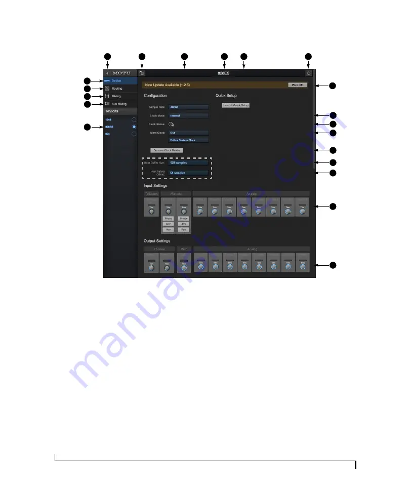
DEVICE TAB
9
6
7
11
12
5
4
3
2
1
8
18
1. If you have two or more MOTU inter-
faces, the Devices list lets you choose
the one you are currently controlling
with the web app.
2. The Aux Mixing tab lets you view
each Aux bus in the mixer, one at a
time.
3. The Mixing tab gives you access to
the mixing and DSP in the interface.
4. The Routing tab displays a grid
matrix, where you can make direct
connections between inputs and
outputs, your computer, the mixer,
and network audio streams, if
networked interfaces are connected.
5. The Device tab has settings for the
hardware itself, such as analog input
and output trim.
6. Expands and collapses the sidebar.
7. Lets you create, save, recall and
manage presets for the 828es. These
presets capture and recall the
complete state of the device (all
settings in all tabs).
8. Choose the desired sample rate.
Make sure your host audio software
is set to the same rate.
9. Click to rename the interface. To
restore the default name, delete the
current name.
10. The Quick Setup button prompts
factory presets used to configure
your interface for a specific applica-
tion. See chapter 6, “Presets”
(page 53).
11. Click this device ID button to identify
the unit you are currently viewing
and controlling with the web app
software. The front panel LCD on the
hardware itself will flash the name
of the device, and its name will also
flash in the Device list (1).
12. If an update is available for your
device, and the computer you are
viewing it from is connected to the
internet, you’ll be notified here. Click
More Info to learn what’s new and
start the update process. Firmware
updating requires a USB or network
connection to your computer. See
Appendix D, “Updating Firmware”
page (113).
13. Choose the clock source from the
Clock Mode menu. Your MOTU
device will resolve its digital clock to
this master source.
14. The Clock Status icon indicates that
the current device (1) is successfully
resolved to its chosen Clock Mode
source (13). If it cannot lock for some
reason, this icon flashes red. Check
your chosen clock source, cables, etc.
15. The Word Clock output on the your
MOTU interface can operate as an
OUT or a THRU. In addition, at higher
sample rates, it can either follow the
system clock or operate at the corre-
sponding 1x sample rate. For details,
see “Daisy-chaining word clock” on
page 48.
16. If you have multiple MOTU inter-
faces, one of them may serve as a
master clock source for the network.
Click the
Become Clock Master
button
to choose the current interface (1) as
the master clock source.
17. (Windows only) Choose the Host
Buffer Size. Smaller values reduce
latency but increase your computer’s
CPU load. See “Host Buffer Size” on
page 30.
18. (Windows only) Choose a Host
Safety Offset to fine tune host buffer
latency. See “Host Safety Offset” on
page 31.
19. The Input Settings section provides
gain settings for inputs and the
built-in talkback mic, plus phase
invert for the mic/guitar inputs. You
can also toggle the 48V phantom
power and -20 dB pad for the mic
inputs.
20. The Output Settings section lets you
adjust the trim for any outputs that
support it. Phones and Main outputs
provide full volume control. Analog
outputs provide calibration control
(-24 to 0 dB).
15
14
10
13
19
Windows only
16
17
20
Summary of Contents for 828es
Page 5: ...Part1 GettingStarted...
Page 6: ......
Page 8: ...8...
Page 22: ...M O T U P R O A U D I O C O N T R O L W E B A P P 22...
Page 28: ...P A C K I N G L I S T A N D S Y S T E M R E Q U I R E M E N T S 28...
Page 32: ...S O F T W A R E I N S T A L L A T I O N 32...
Page 51: ...Part2 Usingthe828es...
Page 52: ......
Page 62: ...F R O N T P A N E L O P E R A T I O N 62...
Page 78: ...M I X E R E F F E C T S 78...
Page 94: ...M O T U A U D I O T O O L S 94...
Page 101: ...Part3 Appendices...
Page 102: ......
Page 108: ...A P P E N D I X B A U D I O S P E C I F I C A T I O N S 108...
Page 109: ...APPENDIX 109 C Mixer Schematics MONO INPUT CHANNEL...
Page 110: ...A P P E N D I X C M I X E R S C H E M A T I C S 110 STEREO INPUT CHANNEL...
Page 111: ...A P P E N D I X C M I X E R S C H E M A T I C S 111 GROUP BUS...
Page 112: ...A P P E N D I X C M I X E R S C H E M A T I C S 112 MONITOR BUS...
Page 116: ...A P P E N D I X E O S C S U P P O R T 116...
Page 120: ...I N D E X 120...


