


7 Wiring and Configuration
60
Rev. 06/2021
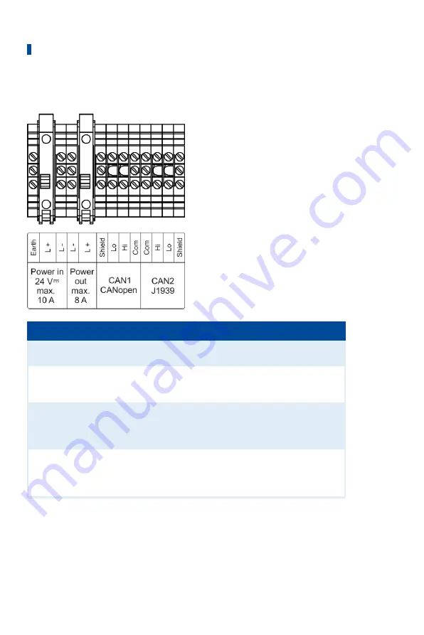
Do the wiring as follows:
Designation
Function
Power in
24 V
⎓
Earth,
L +, L –
Terminals for the power supply of the EasyNO
ₓ
system
(16 V DC to 32 V DC, nominal voltage 24 V DC)
Power out
L –, L +
Terminals for passing through the supply voltage to the
first CAN bus/NO
X
sensor module (e.g. via the CAN bus
hybrid cable from MOTORTECH)
CAN1
CANopen
Shield, Lo,
Hi, Com
Terminals of the CAN bus interface CAN1 (protocol CAN-
open
®
) for connection to the devices in the CANopen
®
network including the optional I/O communication mod-
ules (see
CAN Bus Wiring CAN1
on page 67)
CAN2
J1939
Com, Hi, Lo,
Shield
Terminals of the CAN bus interface CAN2 (protocol
J1939) for connection to the first CAN bus/NO
X
sensor
module (e.g. via the CAN bus hybrid cable from MOTOR-
TECH)
Use suitable wire end ferrules (not supplied) for each wire that you place on a terminal.
Use a three-core round cable with a minimum cross section of 1.5 mm
2
to connect the EasyNO
ₓ
system to the power supply. The earth of the EasyNO
ₓ
system must be connected to the earth of
the system.
Only use shielded CAN cables for CAN bus wiring, and connect the shields to the appropriate ter-
minals (
Shield
).
Summary of Contents for EasyNOx
Page 1: ...EasyNOX NOX Monitoring Operating Manual P N 01 50 026 EN Rev 06 2021 ...
Page 33: ...4 Product Description Rev 06 2021 33 4 1 7 Overview Drawings 4 1 7 1 Dimensions EasyNOX ...
Page 34: ...4 Product Description 34 Rev 06 2021 ...
Page 35: ...4 Product Description Rev 06 2021 35 CAN Bus NOX Sensor Module P N 63 05 015 ...
Page 36: ...4 Product Description 36 Rev 06 2021 I O Communication Module Optional ...
Page 142: ......


