Transceiver Performance Testing
Test Mode
3-7
* See Table 3-3
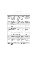
Table 3-5. Receiver Performance Checks
Test Name
Communications
Analyzer
Radio
Test Set
Comments
Reference
Frequency
Mode: PWR MON
4th channel test
frequency*
Monitor: Frequency error
Input at RF In/Out
TEST MODE,
Test Channel
4 carrier
squelch
output at
antenna
PTT to
continuously
transmit (during the
performance
check)
Frequency error to be
±201Hz for UHF
±68Hz for VHF
Rated Audio
Mode: GEN
Output level: 1.0mV RF
6th channel test
frequency*
Mod: 1kHz tone at
3kHz deviation
Monitor: DVM: AC Volts
TEST MODE
Test Channel
6 carrier
squelch
PTT to OFF
(center), meter
selector to Audio
PA
Set volume
control to 0.4 Vrms
(Through audio jack)
Distortion
As above, except to
distortion
As above
As above
Distortion <5.0%
Sensitivity
(SINAD)
As above, except
SINAD, lower the RF
level for 12dB SINAD.
As above
PTT to OFF
(center)
RF input to be
<0.3
μ
V
Noise Squelch
Threshold
(only radios
with
conventional
system need
to be tested)
RF level set to 1mV RF
As above
PTT to OFF
(center), meter
selection to Audio
PA, speaker/load to
speaker
Set volume
control to 0.4 Vrms
(Through audio jack)
As above, except change
frequency to a
conventional system.
Raise RF level from zero
until radio unsquelches.
Out of TEST
MODE;
select a
conventional
system
As above
Unsquelch to occur at
<0.25
μ
V.
Preferred SINAD = 9
– 10dB
Receiver
BER
IFR DMR mode. Signal
generator with O.153 test
pattern
TEST MODE,
Digital Mode,
transmit with
O.153 test
pattern
Read BER using
Tuner. Adjust RF
level to get 5%
BER
RF level to be
<0.25
μ
V for 5% BER
Receiver
Rated Audio
IFR DMR Mode. Signal
generator with 1031 test
pattern
Test Mode,
Digital Mode,
receive 1031
test pattern
RF level = -47dBm.
Set audio analyzer
to read Vrms.
Adjust volume to
get rated audio
Adjust volume until
Vrms = 0.4 V
(Through audio jack)
Receiver
Audio
Distortion
IFR DMR Mode. Signal
generator with 1031 test
pattern
As above
As above. Then set
audio analyzer to
measure distortion
Not exceed 5%
Final Draft
Summary of Contents for SL1M
Page 1: ...tTitle Page SL1M Portable Radio Basic Service Manual MN000916A01 AA tttt Final Draft ...
Page 2: ...Final Draft ...
Page 4: ...Notes Final Draft ...
Page 6: ...vi Notes Final Draft ...
Page 10: ...x Table of Contents Notes Final Draft ...
Page 12: ...xii List of Figures Notes Final Draft ...
Page 14: ...xiv List of Tables Notes Final Draft ...
Page 16: ...xvi List of Tables Notes Final Draft ...
Page 36: ...Notes 2 6 Test Equipment and Service Aids Audio Test Cable Final Draft ...
Page 46: ...Notes 3 10 Transceiver Performance Testing Test Mode Final Draft ...
Page 50: ...Notes 4 4 Radio Programming and Tuning Radio Tuning Setup Final Draft ...
Page 78: ...Notes 5 28 Disassembly And Reassembly Procedures Torque Chart Final Draft ...
Page 82: ...Notes 6 4 Basic Troubleshooting Operational Error Codes Final Draft ...
Page 89: ...Final Draft ...

