


Chapter 3 Transceiver Performance Testing
3.1
General
These radios meet published specifications through their manufacturing process by utilizing high
accuracy laboratory-quality test equipment. The recommended field service equipment approaches
the accuracy of the manufacturing equipment with few exceptions.
3.2
Setup
Supply voltage is provided using a 3.7 VDC power supply. The equipment required for alignment
procedures is connected as shown in the Radio Tuning Equipment Setup Diagram, Figure 4-4.
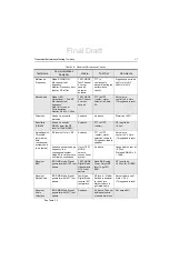
The initial equipment control settings is shown in Table 3-1. The remaining tables in this chapter
contain the following related technical data:
Do NOT use any form of connector, e.g. wires, crocodile
clips, and probes, to supply voltage to the radio, other
than the Motorola approved battery eliminator.
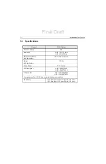
Table Number
Title
Initial Equipment Control Settings
Test Environments
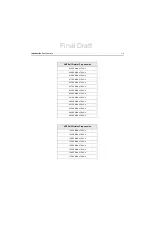
Test Frequencies
Transmitter Performance Checks
Receiver Performance Checks
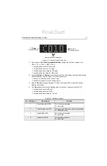
Table 3-1. Initial Equipment Control Settings
Service Monitor
Power Supply
Test Set
Monitor Mode: Power Monitor
Voltage: 3.7 Vdc
Speaker Set: A
RF Attn: -70
DC on/standby: Standby
Speaker/load: Speaker
AM, CW, FM: FM
Voltage Range: 4.44 V
PTT: OFF
Final Draft
Summary of Contents for SL1M
Page 1: ...tTitle Page SL1M Portable Radio Basic Service Manual MN000916A01 AA tttt Final Draft ...
Page 2: ...Final Draft ...
Page 4: ...Notes Final Draft ...
Page 6: ...vi Notes Final Draft ...
Page 10: ...x Table of Contents Notes Final Draft ...
Page 12: ...xii List of Figures Notes Final Draft ...
Page 14: ...xiv List of Tables Notes Final Draft ...
Page 16: ...xvi List of Tables Notes Final Draft ...
Page 36: ...Notes 2 6 Test Equipment and Service Aids Audio Test Cable Final Draft ...
Page 46: ...Notes 3 10 Transceiver Performance Testing Test Mode Final Draft ...
Page 50: ...Notes 4 4 Radio Programming and Tuning Radio Tuning Setup Final Draft ...
Page 78: ...Notes 5 28 Disassembly And Reassembly Procedures Torque Chart Final Draft ...
Page 82: ...Notes 6 4 Basic Troubleshooting Operational Error Codes Final Draft ...
Page 89: ...Final Draft ...


