background image

3-8

Transceiver Performance Testing

: Test Mode

3.3.4

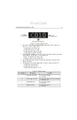
LED Status Test Mode

3.3.4.1  Display Model

1. Press and hold the 

Side Programmable Button

, to switch from RF Test Model to LED 

Status Test Mode.

2. The radio beeps once, and display shows LED.
3. Upon any button press 

(

Side Programmable Button

 or 

/– Button

), 

the radio’s 

RED LED lights up.

4. Any button press following the RED LED check, turns on the GREEN LED.
5. Any button press following the GREEN LED check, turns on both the LEDs.

NOTE:

Do not use the 

ON/OFF Button

, to change the LED status.

3.3.5

LED Display Matrix Test Mode

3.3.5.1  Display Model

1. Press and hold the 

Side Programmable Button

, to switch from LED Status Test Mode, to 

LED Display Matrix Test Mode.

2. The radio beeps once.
3. Upon any button press at first time, LEDs will be turned on and displayed in a column format. 

There are total of 19 columns, moving from Left to Right.

4. Upon any following button press, LEDs will be turned on and displayed in a row format. There 

are total of 5 rows, moving from Top to Bottom.

5. Upon any following button press, all LEDs will be turned on at once.

3.3.6

Speaker Tone Test Mode

3.3.6.1  Display Model

1. Press and hold the 

Side Programmable Button,

 to switch the radio from LED Display Matrix 

Test Mode to Speaker Tone Test Mode.

2. The radio beeps once, and 1 kHz tone is heard from the internal speaker.
3. The radio display shows SKPR.

3.3.7

Earpiece Tone Test Mode

3.3.7.1  Display Model

1. Press and hold the 

Side Programmable Button

, to switch from Speaker Tone Test Mode to 

External Earpiece Tone Test Mode.

2. The radio beeps once, and 1 kHz tone is heard from the earpiece.
3. The radio display shows EAR.

3.3.8

Audio Loopback Earpiece Test

3.3.8.1  Display Model

1. Press and hold the 

Side Programmable Button

, to switch from Earpiece Tone Test Mode, to 

Audio Loopback Earpiece Test Mode.

2. The radio beeps once.

Final Draft

Summary of Contents for SL1M

Page 1: ...tTitle Page SL1M Portable Radio Basic Service Manual MN000916A01 AA tttt Final Draft ...

Page 2: ...Final Draft ...

Page 3: ...oppel or otherwise any license under the copyrights patents or patent applications of Motorola except for the normal non exclusive license to use that arises by operation of law in the sale of a product Document Copyrights No duplication or distribution of this document or any portion thereof shall take place without the express written permission of Motorola No part of this manual may be reproduc...

Page 4: ...Notes Final Draft ...

Page 5: ...v Document History The following major changes have been implemented in this manual since the previous edition Edition Description Date MN000916A01 AA Initial Release Sept 2014 Final Draft ...

Page 6: ...vi Notes Final Draft ...

Page 7: ...s Not Cover xviii VI Patent And Software Provisions xix VII Governing Law xix Battery and Charger Warranty xx Workmanship Warranty xx Capacity Warranty xx Chapter 1 Introduction 1 1 1 1 Notations Used in This Manual 1 1 1 2 Radio Description 1 1 1 2 1 Radio Overview 1 2 1 3 Portable Radio Model Numbering Scheme 1 3 1 4 Model Charts 1 4 1 4 1 VHF 136 174 MHz 2 3W Model Chart 1 4 1 4 2 UHF 403 470 M...

Page 8: ...play Model 3 9 Chapter 4 Radio Programming and Tuning 4 1 4 1 Introduction 4 1 4 2 Customer Programming Software Setup 4 1 4 3 AirTracer Application Tool 4 3 4 4 Radio Tuning Setup 4 3 Chapter 5 Disassembly And Reassembly Procedures 5 1 5 1 Introduction 5 1 5 2 Preventive Maintenance 5 1 5 2 1 Inspection 5 2 5 2 2 Cleaning Procedures 5 2 5 3 Safe Handling of CMOS and LDMOS Devices 5 3 5 4 Repair P...

Page 9: ...r Reassembly 5 24 5 8 Radio Exploded Mechanical Views and Parts Lists 5 25 5 9 Torque Chart 5 27 Chapter 6 Basic Troubleshooting 6 1 6 1 Introduction 6 1 6 2 Power Up Error Codes 6 1 6 3 Operational Error Codes 6 3 Appendix A EMEA Regional Warranty Service and Technical Support A 1 A 1 Warranty and Service Support A 1 A 1 1 Warranty Period and Return Instructions A 1 A 1 2 After Warranty Period A ...

Page 10: ...x Table of Contents Notes Final Draft ...

Page 11: ...3 Audio Jack Speaker Micro USB Microphone Flex and Display Flex Disassembly 5 12 Figure 5 14 Internal Frame Screws Disassembly 5 13 Figure 5 15 Internal Frame Disassembly 5 13 Figure 5 16 Speaker Disassembly 5 14 Figure 5 17 Display Module Disassembly 5 14 Figure 5 18 Internal Antenna Disassembly 5 15 Figure 5 19 Dust Cover Head Removal 5 15 Figure 5 20 Dust Cover Removal 5 16 Figure 5 21 Dust Cov...

Page 12: ...xii List of Figures Notes Final Draft ...

Page 13: ...Table 3 1 Initial Equipment Control Settings 3 1 Table 3 2 Test Environments 3 3 Table 3 3 Test Frequencies 3 4 Table 3 4 Transmitter Performance Checks 3 5 Table 3 5 Receiver Performance Checks 3 7 Table 4 1 Software Installation Kits Radio Tuning Setup 4 1 Table 5 1 Lead Free Solder Wire Part Number List 5 4 Table 5 2 Lead Free Solder Paste Part Number List 5 4 Table 5 3 SL1600 Exploded View Par...

Page 14: ...xiv List of Tables Notes Final Draft ...

Page 15: ...ure 6804110J47 Multi Unit Charger User Guide 6866552D01 Quick Reference Guide Product Safety and RF Exposure 68009553001 MOTOTRBO SL1M Portable User Guide MN000892A01 MOTOTRBO SL1M Portable Quick Reference Guide MN000899A01 MOTOTRBO SL1M CMM Leaflet MN000898A01 Final Draft ...

Page 16: ...xvi List of Tables Notes Final Draft ...

Page 17: ...TOROLA and the original end user purchaser MOTOROLA does not warrant the installation maintenance or service of the Product MOTOROLA cannot be responsible in any way for any ancillary equipment not furnished by MOTOROLA which is attached to or used in connection with the Product or for operation of the Product with any ancillary equipment and all such equipment is expressly excluded from this warr...

Page 18: ...ance installation alteration modification or adjustment D Breakage or damage to antennas unless caused directly by defects in material workmanship E A Product subjected to unauthorized Product modifications disassemblies or repairs including without limitation the addition to the Product of non Motorola supplied equipment which adversely affect performance of the Product or interfere with Motorola...

Page 19: ...Product or parts as established by MOTOROLA MOTOROLA will have no liability with respect to any claim of patent infringement which is based upon the combination of the Product or parts furnished hereunder with software apparatus or devices not furnished by MOTOROLA nor will MOTOROLA have any liability for the use of ancillary equipment or software not furnished by MOTOROLA which is attached to or ...

Page 20: ...workmanship warranty guarantees against defects in workmanship under normal use and service Capacity Warranty The capacity warranty guarantees 80 of the rated capacity for the warranty duration Battery Lilon 2200mAh 12 Months Chargers 12 Months Battery Lilon 2200mAh 12 Months Final Draft ...

Page 21: ...ormance quality and reliability in their daily communications This architecture provides the capability of supporting a multitude of legacy and advanced features resulting in a more cost effective two way radio communications solution NOTE An operational procedure practice or condition that is essential to emphasize CAUTION indicates a potentially hazardous situation which if not avoided might res...

Page 22: ...ions PUSH TO TALK PTT BUTTON Press to execute voice operations e g Group call and Private Call ANTENNA Provides the needed RF amplification when transmitting or receiving MICROPHONE Allows voice to be sent when PTT or voice operations are activated ACCESSORY CONNECTOR Interface point for audio accessories to be used with the radio USB Programs the radio through a computer and charges the radio thr...

Page 23: ... 4 5 6 7 8 9 10 11 12 Unique Variation N Standard Package Version Letter Feature Level 2 Non FM Primary System Type A Conventional Primary Operation J Basic Channel Spacing 9 Variable Programmable Power Level C 2W 3W 88 SL Series Band Q 403 470MHz J 136 174MHz Physical Packages P LED Matrix Display No Keypad C Plain Model H Portable AZ APAC Australia LA Latin America AA North America MD EMEA Final...

Page 24: ...sembly X PMLD4696_S Main Board Assembly Service Kit X PMAD4144_ VHF stubby antenna 136 144 MHz X PMAD4145_ VHF stubby antenna 144 156 MHz X PMAD4146_ VHF stubby antenna 156 174 MHz X Item Included _ The latest version kit When ordering a kit refer to your specific kit for the suffix number See A 3 Additional Service Kits Information on page A 2 for guidelines on selecting the appropriate Service K...

Page 25: ...bly X X PMLE5020_S Main Board Assembly Service Kit X X PMAE4093_ UHF stubby antenna 403 425 MHz X X PMAE4094_ UHF stubby antenna 420 445 MHz X X PMAE4095_ UHF stubby antenna 435 470 MHz X Item Included _ The latest version kit When ordering a kit refer to your specific kit for the suffix number See A 3 Additional Service Kits Information on page A 2 for guidelines on selecting the appropriate Serv...

Page 26: ...tery 125 7 x 55 0 x 22 0 mm Weight with Lilon battery 163 4g Power Supply 3 7 V nominal FCC Description VHF AZ489FT3835 UHF AZ489FT4922 IC Description VHF 109U 89FT3835 UHF 109U 89FT4922 Average battery life at 5 5 90 duty cycle with battery saver enabled Lilon battery VHF Analogue 12 3 hours Digital 14 5 hours UHF Analogue 12 3 hours Digital 14 5 hours Final Draft ...

Page 27: ...igital Sensitivity 5 BER 0 25 µV 0 19 µV typical Intermodulation TIA603D 70 dB Adjacent Channel Selectivity TIA603D 45 dB 12 5 kHz 70 dB 25 kHz Spurious Rejection TIA603D 70 dB Rated Audio 0 5 W internal Audio Distortion Rated Audio 5 3 typical Hum and Noise 40 dB 12 5 kHz 45 dB 25 kHz Audio Response TIA603D Conducted Spurious Emission 57 dBm Speaker Impedance 4 Ohms internal Voltage Rated Audio 1...

Page 28: ... kHz 12 5 kHz 5 0 kHz 25 kHz FM Hum and Noise 40 dB 12 5 kHz 45 dB 25 kHz Conducted Radiated Emission 36 dBm 1 GHz 30 dBm 1 GHz Adjacent Channel Power 60 dB 12 5 kHz 70 dB 25 kHz Audio Response TIA603D Audio Distortion 3 typical 4FSK Digital Modulation 12 5 kHz Data 7K60F1D 7K60FXD 12 5 kHz Voice 7K60F1E 7K60FXE Combination of 12 5 kHz Data Voice 7K60F1W Digital Vocoder Type AMBE 2 Digital Protoco...

Page 29: ...Hz 427 20 MHz 10 kHz 432 00 MHz 20 kHz 436 80 MHz 10 kHz 441 60 MHz 20 kHz 446 40 MHz 10 kHz 451 20 MHz 20 kHz 456 00 MHz 10 kHz 460 80 MHz 20 kHz 465 60 MHz 10 kHz VHF Self Quieter Frequencies 139 20 MHz 10 kHz 144 00 MHz 10 kHz 148 80 MHz 10 kHz 153 60 MHz 10 kHz 158 40 MHz 10 kHz 163 20 MHz 10 kHz 168 00 MHz 15 kHz 172 80 MHz 10 kHz Final Draft ...

Page 30: ...II 505 2 I 505 3 I 505 4 I 505 5 I A1 Rain 506 1 I II 506 2 I II 506 3 I II 506 4 I III 506 5 I III Humidity 507 1 II 507 2 II 507 3 II 507 4 507 5 II Agg Salt fog 509 1 I 509 2 I 509 3 I 509 4 509 5 Dust 510 1 I 510 2 I 510 3 I 510 4 I 510 5 I Vibration 514 2 VIII F W 514 3 I I0 II 3 514 4 I 10 II 3 514 5 I 24 514 6 I 24 Shock 516 2 I III V 516 3 I IV VI 516 4 I IV VI 516 5 I IV VI 516 6 I IV VI ...

Page 31: ...nt measurements Audio voltage measurements RF Signal Generator 100 MHz to 1 GHz 130 dBm to 10 dBm FM Modulation 0 kHz to 10 kHz Audio Frequency 100 Hz to 10 kHz Agilent 443X R S Signal Generator Receiver measurements Oscilloscope 2 Channel 50 MHz Bandwidth 5 mV div to 20 V div Leader LS8050 www leaderusa com Tektronix TDS1001b www tektronix com or equivalent Waveform measurements Power Meter and S...

Page 32: ...adio s antenna port to test equipment HW000406A01 RF Antenna Adaptor Holder Holds the RF antenna adaptor HW000405A01 Battery Eliminator Connects to radio via battery eliminator cable PMVN4130_ MOTOTRBO CPS AirTracer CD CPS allows Dealers Distributors to program radio parameters AirTracer allows the capturing of radio traffic into logs for analysis by Motorola PMVN4131_ MOTOTRBO Tuner CD This tuner...

Page 33: ...rogramming Cable Figure 2 1 Portable Programming Cable with TTR PMKN4128_ Table 2 3 Pin Configuration of Portable Programming Cable with TTR CONNECTION P1 P2 P3 Function 1 1 VCC 5V 2 2 DATA 3 3 DATA 4 BNC Center Pin TTR 5 4 BNC Shell GROUND P2 1 4 P3 P1 1 5 2 1 3 5 4 Final Draft ...

Page 34: ... Cable 2 4 Micro USB Programming Cable Figure 2 2 Micro USB Programming Cable CB000262A01 Table 2 4 Pin Configuration of Micro USB Programming Cable CONNECTION CONN 1 CONN 2 Function 1 1 VBUS 2 2 DATA 3 3 DATA 5 4 GROUND CONN 1 CONN 2 P5 P1 P4 P1 Final Draft ...

Page 35: ...dio Test Cable 2 5 2 5 Audio Test Cable Figure 2 3 Audio Test Cable CB000233A01 Table 2 5 Pin Configuration of Audio Test Cable CONNECTION P1 P2 Function 1 5 2 SPK 17 1 MIC 2 7 16 3 MIC SPK 20 5 PTT CONN 1 CONN 2 P5 P1 P4 P1 Final Draft ...

Page 36: ...Notes 2 6 Test Equipment and Service Aids Audio Test Cable Final Draft ...

Page 37: ...nt control settings is shown in Table 3 1 The remaining tables in this chapter contain the following related technical data Do NOT use any form of connector e g wires crocodile clips and probes to supply voltage to the radio other than the Motorola approved battery eliminator Table Number Title Table 3 1 Initial Equipment Control Settings Table 3 2 Test Environments Table 3 3 Test Frequencies Tabl...

Page 38: ... Mode 3 3 3 1 Display Model 1 Upon entering RF Test Mode the display shows RF for 2 seconds and then shows the default channel profile 2 The default channel profile is CSQ CH1 and 12 5 kHz For an example C010 is for CSQ CH1 and 12 5 kHz First character indicates the Test Environment Second and third character indicates the Channel Index Fourth character indicates the Channel Spacing Oscilloscope S...

Page 39: ...9 to channel 16 is for TX High Power 5 Sway the Rocker to change between 12 5 kHz 20 kHz and 25 kHz after the Channel Selection Test Mode 6 The Display shows the channel spacing value for 1 second and reverts back to CH1 The radio beeps once for 20 kHz The radio beeps twice for 25 kHz The radio beeps three times for 12 5 kHz Table 3 2 Test Environments No of Beeps Description Function 1 Carrier Sq...

Page 40: ...42 575 3 Low Power 11 High Power TX 3 or 11 RX 3 or 11 425 150 425 150 146 575 146 575 4 Low Power 12 High Power TX 4 or 12 RX 4 or 12 436 450 436 450 155 575 155 575 5 Low Power 13 High Power TX 5 or 13 RX 5 or 13 447 150 447 150 161 575 161 575 6 Low Power 14 High Power TX 6 or 14 RX 6 or 14 458 150 458 150 167 575 167 575 7 Low Power 15 High Power TX 7 or 15 RX 7 or 15 469 850 469 850 173 975 1...

Page 41: ...s above As above meter selector to mic Deviation 4 0 kHz but 5 0 kHz 25 kHz Ch Sp Voice Modulation internal Mode PWR MON 4th channel test frequency atten to 70 input to RF In Out TEST MODE Test Channel 4 carrier squelch output at antenna Remove modulation input Press PTT switch on radio Say four loudly into the radio mic Measure deviation 4 0 kHz but 5 0 kHz 25 kHz Ch Sp TPL Modulation As above 4t...

Page 42: ... error As above As above Not Exceed 1 Symbol Deviation DMR Mode Symbol Deviation As above As above Symbol Deviation should be within 648Hz 10 and 1944Hz 10 Transmitter BER DMR Mode As above As above Transmitter BER should be 0 Test Name Communications Analyzer Radio Test Set Comments Final Draft ...

Page 43: ...0 3μV Noise Squelch Threshold only radios with conventional system need to be tested RF level set to 1mV RF As above PTT to OFF center meter selection to Audio PA speaker load to speaker Set volume control to 0 4 Vrms Through audio jack As above except change frequency to a conventional system Raise RF level from zero until radio unsquelches Out of TEST MODE select a conventional system As above U...

Page 44: ...There are total of 19 columns moving from Left to Right 4 Upon any following button press LEDs will be turned on and displayed in a row format There are total of 5 rows moving from Top to Bottom 5 Upon any following button press all LEDs will be turned on at once 3 3 6 Speaker Tone Test Mode 3 3 6 1 Display Model 1 Press and hold the Side Programmable Button to switch the radio from LED Display Ma...

Page 45: ...st Mode 2 The radio beeps once 3 The radio s LED indicator shows GREEN for High battery level AMBER for Mid battery level and RED for Low battery level 4 The radio display shows BATT 3 3 10 Button Test Mode 3 3 10 1 Display Model 1 Press and hold the Side Programmable Button to switch from Battery Check Test Mode to Button Test Mode 2 Upon any button press the radio beeps once 3 The radio display ...

Page 46: ...Notes 3 10 Transceiver Performance Testing Test Mode Final Draft ...

Page 47: ... Customer Programming Software Setup The CPS programming setup shown in Figure 4 1 is used to program the radio Figure 4 1 CPS Programming Setup NOTE Refer to the appropriate program on line help files for the programming procedures Description Kit Number MOTOTRBO CPS Tuner and AirTracer Applications CD PMVN4130_ PMVN4131_ NOTE Refer to the appropriate program on line help files for the programmin...

Page 48: ...ing Customer Programming Software Setup Figure 4 2 Connecting RF Antenna Adaptor To Radio RF Input Output Port Figure 4 3 RF Plug RF antenna adaptor holder HW000406A01 RF antenna adaptor 28012039001 RF plug EN000047A01 Final Draft ...

Page 49: ...ich will need to be set for the appropriate final device bias prior to keying up the radio If the bias is not properly set it may be possible to cause damage to the transmitter NOTE Refer to the appropriate program online help files for the tuning procedures A personal computer PC Windows 7 or Windows 8 and a tuner program are required to tune the radio To perform the tuning procedures the radio m...

Page 50: ...Notes 4 4 Radio Programming and Tuning Radio Tuning Setup Final Draft ...

Page 51: ...inspection and cleaning Safe handling of CMOS and LDMOS devices Repair procedures and techniques Disassembly and re assembly of the radio 5 2 Preventive Maintenance Periodic visual inspection and cleaning is recommended Only Motorola Service Centers or Authorized Motorola Service Dealers can perform this function C a u t i o n Final Draft ...

Page 52: ...olution and dry the radio Make sure that no water remains entrapped near the connectors cracks or crevices Cleaning Internal Circuit Boards and Components Isopropyl alcohol 100 may be applied with a stiff non metallic short bristled brush to dislodge embedded or caked materials located in hard to reach areas The brush stroke should direct the dislodged material out and away from the inside of the ...

Page 53: ...at all exposed leads are shorted together Do not insert CMOS LDMOS devices into conventional plastic snow trays used for storage and transportation of other semiconductor devices Ground the working surface of the service bench to protect the CMOS LDMOS device We recommend using the Motorola Static Protection Assembly part number 0180386A82 which includes a wrist strap two ground cords a table mat ...

Page 54: ...er bridges between the connector pins Examine your work closely for shorts due to solder bridges For soldering components with Hot Air or infra red solder systems please check your user guide of the solder system to get information on solder temperature and time for the different housings of the integrated circuits and other components NOTE Environmentally Preferred Products EPP refer to the marki...

Page 55: ... The following tools are required for disassembling and reassembling the radio T06 Torx Plus Torque wrench Tweezer If a unit requires further testing or service than is customarily performed at the basic level please send the radio to a Motorola Service Center Appendix A To assure the safety and regulatory compliance of the SL1M the radio must be repaired only at Motorola service facilities Please...

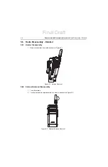
Page 56: ...Detailed 5 6 1 Holster Disassembly 1 Remove the holster from radio as shown in Figure 5 1 Figure 5 1 Holster Removal 5 6 2 External Antenna Disassembly 1 Turn off the radio 2 Turn the antenna counterclockwise to remove it as shown in Figure 5 2 Figure 5 2 External Antenna Removal Final Draft ...

Page 57: ...ack Housing Disassembly 1 Remove the 2 screw plugs from the back housing as shown in Figure 5 3 NOTE Remove the screw plug with plastic tweezer Figure 5 3 Screw Plug Removal 2 Remove the RF plug from the back housing as shown in Figure 5 4 Figure 5 4 RF Plug Removal Final Draft ...

Page 58: ...E Remove the RF plug with plastic tweezer 3 Unlock the battery door by sliding the latch to the right as shown in Figure 5 5 Figure 5 5 Unlock The Battery Door 4 Remove the battery door by lifting it upwards as shown in Figure 5 6 Figure 5 6 Battery Door Removal Final Draft ...

Page 59: ...ts battery compartment as shown in Figure 5 7 To remove the battery grasp the battery grove as the bottom of the battery and lift it up NOTE Only battery PMNN4468 can be used for this radio Figure 5 7 Battery Removal 6 Remove the screws by using T06 Torx Plus screwdriver as shown in Figure 5 8 Figure 5 8 Screw Removal Final Draft ...

Page 60: ...assembly Procedures Radio Disassembly Detailed 7 Lift the back housing from the front housing using the Opener Back Housing as shown in Figure 5 10 Figure 5 9 Back Housing Removal Figure 5 10 Back Housing Removal Final Draft ...

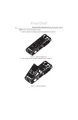
Page 61: ...d Display Flex from the main PCB using plastic tweezers in the direction indicated in Figure 5 11 2 Pull the PCB catch backwards as shown in Figure 5 11 and lift the main PCB upwards as shown in Figure 5 12 Figure 5 11 PCB Catch Disassembly Figure 5 12 Uplifting Of The Main PCB Top Control Flex PTT Flex Display Flex PCB Catch Final Draft ...

Page 62: ...er Micro USB Microphone Flex and Display Flex from the main PCB using plastic tweezers in the direction indicated in Figure 5 13 Figure 5 13 Audio Jack Speaker Micro USB Microphone Flex and Display Flex Disassembly Display Flex Disassembly Audio Jack Speaker Micro USB and Microphone Flex Final Draft ...

Page 63: ...and Internal Antenna Disassembly 1 Remove the internal frame screws by using T06 Torx Plus screwdriver as shown in Figure 5 14 Figure 5 14 Internal Frame Screws Disassembly 2 Lift the internal frame as shown in Figure 5 15 Pull the internal frame out from the front housing as shown in Figure 5 15 Figure 5 15 Internal Frame Disassembly Final Draft ...

Page 64: ...icro USB carefully followed by the microphone the audio jack and the speaker as shown in Figure 5 16 Figure 5 16 Speaker Disassembly 4 Remove the display module by lifting upwards as shown in Figure 5 17 Figure 5 17 Display Module Disassembly Microphone Micro USB Speaker Audio Jack Final Draft ...

Page 65: ...bly Detailed 5 15 5 Remove the internal antenna by lifting upwards as shown in Figure 5 18 Figure 5 18 Internal Antenna Disassembly 5 6 6 Dust Cover Disassembly 1 Cut off the dust cover head Figure 5 19 Dust Cover Head Removal Dust Cover Head Final Draft ...

Page 66: ...er out from the front housing as shown in Figure 5 20 Figure 5 20 Dust Cover Removal 5 7 Radio Reassembly Detailed 5 7 1 Dust Cover Reassembly 1 Insert the dust cover tail into the front housing middle hole openings as shown in Figure 5 21 Figure 5 21 Dust Cover Tail Insertion Final Draft ...

Page 67: ...housing until the head is fully inserted as shown in Figure 5 22 Figure 5 22 Dust Cover Tail Full Insertion Into Housing 3 Cut off the tail with a cutter 5 7 2 Internal Antenna Reassembly 1 Insert the internal antenna into the front housing in direction shown in Figure 5 23 Figure 5 23 Internal Antenna Reassembly Dust cover tail Final Draft ...

Page 68: ...embly 5 7 4 Audio Jack Flex Micro USB Flex Microphone MIC Speaker Flex LCD Display and Internal Antenna Reassembly 1 Insert the Microphone Flex into its recess on the front housing 2 Insert the speaker into the front housing 3 Insert Micro USB Flex into the front housing 4 Insert Audio Jack Flex into the front housing Figure 5 25 Speaker Reassembly Audio Jack Speaker Microphone Micro USB Final Dra...

Page 69: ...nternal frame is properly sits on the front housing ribs as shown in Figure 5 26 Figure 5 26 Internal Frame Reassembly 2 Screw in the internal frame as shown in Figure 5 27 using T06 Torx Plus screwdriver Figure 5 27 Internal Frame Screws Reassembly Do not over torque the screws Please refer to Table 5 4 for screws torque specifications Housing Rib Internal Frame C a u t i o n Final Draft ...

Page 70: ...Audio Jack Speaker Micro USB Microphone Flex and Display Flex Reassembly 3 Insert the main PCB onto the internal frame 4 Attach the Top Control Flex to the connector located at the upper side of the main PCB 5 Attach the PTT Flex to the connector located at upper side of the main PCB 6 Attach the Display Flex to the connector located at the LCD display module Only press on Poron Pad on Top Control...

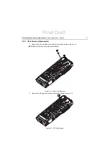
Page 71: ...igure 5 29 Main PCB Reassembly 5 7 7 Back Housing Reassembly 1 Place the back housing onto the front housing as shown in Figure 5 30 and press the back housing towards the front housing Figure 5 30 Back Housing Reassembly Top Control Flex PTT Flex Display Flex Final Draft ...

Page 72: ...06 Torx Plus screwdriver as shown in Figure 5 31 Figure 5 31 Screw Reassembly 3 Insert the battery as shown in Figure 5 32 NOTE Only battery PMNN4468 can be used for this radio Figure 5 32 Battery Reassembly Do not over torque the screws Please refer to Table 5 4 for screws torque specifications C a u t i o n Final Draft ...

Page 73: ...ttach and lock battery door by sliding the latch to the left as shown in Figure 5 33 Figure 5 33 Lock The Battery Door 5 Insert one RF plug and two new screw plugs at the back housing as shown in Figure 5 34 Figure 5 34 Attaching One RF Plug And Two Screw Plugs Final Draft ...

Page 74: ... 8 External Antenna Reassembly 1 Turn the antenna clockwise to engage the antenna to the front housing Figure 5 35 External Antenna Reassembly 5 7 9 Holster Reassembly 1 Attach the holster to radio as shown in Figure 5 36 Figure 5 36 External Antenna Reassembly Final Draft ...

Page 75: ...ures Radio Exploded Mechanical Views and Parts Lists 5 25 5 8 Radio Exploded Mechanical Views and Parts Lists Figure 5 37 SL1MExploded View 1 0 2 1 2 2 2 3 2 4 2 5 3 0 4 0 5 0 6 0 7 0 11 0 2 0 10 0 8 0 9 0 2 6 12 0 2 7 2 8 Final Draft ...

Page 76: ...SB and Microphone Flex Assembly 0104063J28 2 5 Internal Frame Assembly 0104064J28 2 6 Screw Internal Frame 0378212A02 2 7 Display Assembly UHF 0104064J38 VHF 0104064J99 2 8 Dust Cover Audio Jack and Micro USB SL000095A01 3 0 Antenna See Accessory Table 4 0 Thermal Pad 7515526H01 5 0 Main PCB Assembly Display UHF PMLE5020_S Display VHF PMLD4696_S 6 0 Back Housing Assembly UHF PMLE5029_ VHF PMLD4699...

Page 77: ...ommended value when assembling the radio Table 5 4 Torque Specifications for Screws A proper torque screwdriver must be used during installation to ensure that these torque values are not exceeded Part Number Description Qty Driver Socket Torque N m lbs in kgf cm FN000069A01 Main Screw 6 T06 Torx Plus 0 11 0 14 1 0 1 2 1 2 1 4 0378212A02 Screw Internal Frame 4 T06 Torx Plus 0 12 0 15 1 1 1 3 1 3 1...

Page 78: ...Notes 5 28 Disassembly And Reassembly Procedures Torque Chart Final Draft ...

Page 79: ...t Storage blocks that contain operating parameters If the codeplug block operating parameters are corrupted operation of the unit on the proper frequency system and group are in question Attempts to use this information could provide the user with a false sense of security that others are receiving his messages Corrupted codeplug blocks of call IDs or their associated aliases are considered non fa...

Page 80: ...board or send radio to nearest Motorola Depot FAIL 02 84 DSP RAM2 test failure Fatal Retest radio by turning it off and turning it on again If message reoccurs replace main board or send radio to nearest Motorola Depot FAIL 02 88 DSP RAM test failure Fatal Retest radio by turning it off and turning it on again If message reoccurs replace main board or send radio to nearest Motorola Depot FAIL 02 C...

Page 81: ...ay The presence of an error code should prompt a user that a problem exists and that a Motorola Authorized MOTOTRBO dealer should be contacted Use Table 6 2 to aid in understanding any particular operational error codes Table 6 2 Operational Error Codes Error Code Description Error Type Corrective Action FAIL 001 Synthesizer Out of Lock Non Fatal Reprogram the codeplug FAIL 002 Personality checksu...

Page 82: ...Notes 6 4 Basic Troubleshooting Operational Error Codes Final Draft ...

Page 83: ...093_ UHF Stubby Antenna 403 425 MHz 4 5cm PMAE4094_ UHF Stubby Antenna 420 445 MHz 4 5cm PMAE4095_ UHF Stubby Antenna 435 470 MHz 4 5cm PMAD4144_ VHF Stubby Antenna 136 144 MHz 5cm PMAD4145_ VHF Stubby Antenna 144 156 MHz 5cm PMAD4146_ VHF Stubby Antenna 156 174 MHz 5cm Part No Description PMNN4468_ Battery Lilon 2200mAh Part No Description CB000262A01 Micro USB Programming Cable PMKN4128_ Portabl...

Page 84: ... USB Power Supply Adaptor AC DC Switch Mode Wall Cube 5W 100 240 V US Japan Plug PS000042A13 Micro USB Power Supply Adaptor AC DC Switch Mode Wall Cube 5W 100 240 V UK HK Plug PS000042A14 Micro USB Power Supply Adaptor AC DC Switch Mode Wall Cube 5W 100 240 V AUS NZ Plug PS000042A16 Micro USB Power Supply Adaptor AC DC Switch Mode Wall Cube 5W 100 240 V China Plug PS000042A17 Micro USB Power Suppl...

Page 85: ...acement parts or equipment information the complete identification number should be included This applies to all components kits and chassis If the component part number is not known the order should include the number of the chassis or kit of which it is a part and sufficient description of the desired component to identify it Request for help in identification if non referenced spare parts shoul...

Page 86: ...ription AZH88QCP9JA2AN 403 470 MHz 2 3 W SL1M Display Model Item Description X PMUE4541AAMAAA SL1M 403 470M 2 3 W Display Model X PMUE4541AAMACA SL1M 403 438M 2 3 W Display Model X Item Included SL1M VHF 136 174 MHz 2 3 W Model Description AZH88JCP9JA2AN 136 174 MHz 2 3 W SL1M Display Model Item Description X PMUD3334AAMAAA SL1M 136 174M 2 3 W Display Model X Item Included Final Draft ...

Page 87: ...lohertz One thousand cycles per second Used especially as a radio frequency unit LCD Liquid Crystal Display An LCD uses two sheets of polarizing material with a liquid crystal solution between them An electric current passed through the liquid causes the crystals to align so that light cannot pass through them LED Light Emitting Diode An electronic device that lights up when electricity is passed ...

Page 88: ... s preset squelch level can be heard Transceiver Transmitter receiver A device that both transmits and receives digital signals Also abbreviated as XCVR Transmitter Electronic equipment that generates and amplifies an RF carrier signal modulates the signal and then radiates it into space TX Transmit UHF Ultra High Frequency USB Universal Serial Bus An external bus standard that supports data trans...

Page 89: ...Final Draft ...

Reviews: