SPAC-AS-MSV320 Antenna Installation
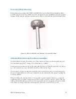
Installation of the 3-axis antenna on the mast is done according to FIG 21. The diameter
of the post shall preferably be between 35 and 50 mm using the standard clamp supplied
in the kit. Note the TORQUES for bolts and nuts.
A small loop should be made on the co-axial cable near the plug SPAC M00233 in order to
be able to pull the cable about 15 cm up through the mounting pole, when the antenna is
installed or removed.
If a long (e.g. 3m) post is used on board a ship it is recommended that this is fastened to the
ship using standard clamps rather than welding. This will enable the post to be laid down in
case removal of the antenna is required.
Vibration
The antennas (2- and 3-axis versions) are designed to meet the following operating vibration
levels in any of three perpendicular directions measured at the mounting base of the radome
i.e. at the flange of the standard mounting pole described above:
Random Vibration
1.05 Grms with the following spectral density
5-20 Hz………….0.02G2/Hz
20-150 Hz……….-3dB/octave
And further,
Single Frequency Vibration
5-10 Hz with amplitude 2.54 mm
10-15 Hz with amplitude 0.76mm
15-25 Hz with amplitude 0.40mm
25-33 Hz with amplitude 0.23mm
Vibration levels in a typical installation are usually much less than the above mentioned
values. It is, however, the responsibility of the installer to verify that the cited levels are not
exceeded in any mode of operation of the vehicle/vessel. In case of abnormal vibration,
typically at a resonance frequency, measures much be taken in order to displace the
resonance frequency or to dampen the vibration amplitude.
MSAT-G2 Installation Guide
21
Summary of Contents for MSAT-G2
Page 1: ......

