viii
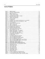
List of Tables
List of Tables
Table 2-1.
IMPRES Batteries ................................................................................................................. 2-1
Table 2-2.
Transceiver Voltage Regulators ............................................................................................ 2-3
Table 3-1.
Battery Connector J3 ............................................................................................................ 3-6
Table 3-2.
VOCON Connector J1001 .................................................................................................... 3-7
Table 3-3.
Port Expander Pin Settings ................................................................................................. 3-24
Table 3-4.
DC Supplies and Sources for Controller ............................................................................. 3-34
Table 3-5.
MAKO’s LDO and Supplies................................................................................................. 3-35
Table 3-6.
VOCON Clock Distribution .................................................................................................. 3-38
Table 3-7.
LED Color Codes ................................................................................................................ 3-51
Table 3-8.
Key Map Matrix ................................................................................................................... 3-54
Table 3-9.
Side Button Flex Connector Pin Assignment – P1 and J2005 ............................................ 3-55
Table 3-10. Side Button Flex Connector Pin Assignment – P2001........................................................ 3-56
Table 3-11. P1 Pin Assignment.............................................................................................................. 3-58
Table 3-12. GCAI Connector Pin Assignment........................................................................................ 3-58
Table 3-13. J2004 Pin Assignment ........................................................................................................ 3-59
Table 3-14. P2001 Pin Assignment........................................................................................................ 3-60
Table 3-15. Bluetooth Module Signal Summary..................................................................................... 3-64
Table 3-16. Bluetooth Module IO Summary ........................................................................................... 3-65
Table 3-17. Bluetooth Module MMC Signals.......................................................................................... 3-66
Table 3-18. J3001 Bluetooth Interface Connector ................................................................................. 3-67
Table 4-1.
Recommended Service Tools ............................................................................................... 4-2
Table 4-2.
Standard Operating Bias – DC Voltages ............................................................................... 4-3
Table 4-3.
Standard Operating Bias – Clock Sources............................................................................ 4-3
Table 4-4.
Power-Up Self-Check Error Codes ....................................................................................... 4-4
Table 4-5.
Power-Up Self-Check Diagnostic Actions............................................................................. 4-5
Table 5-1.
Troubleshooting Charts List .................................................................................................. 5-1
Table 6-1.
List of Waveforms ................................................................................................................. 6-1
Table 7-1.
List of Tables of Board and IC Signals .................................................................................. 7-1
Table 7-2.
J1001 VOCON Board to RF Board ....................................................................................... 7-2
Table 7-3.
J4001 VOCON Board to Expansion Board ........................................................................... 7-3
Table 7-4.
J2101 VOCON Board to Control Top .................................................................................... 7-4
Table 7-5.
J2301 VOCON Board (MNCN6200) to Front Chassis .......................................................... 7-5
Table 7-6.
J2301 VOCON Board (MNCN6202) to Front Chassis .......................................................... 7-6
Table 7-7.
J2004 Expansion Board to GCAI .......................................................................................... 7-7
Table 7-8.
J2005 Expansion Board to Side Buttons............................................................................... 7-7
Table 7-9.
J2101 Expansion Board to Memory Card (Slot).................................................................... 7-8
Table 7-10. Expansion Board to Front Internal Speaker and Mic............................................................. 7-8
Table 7-11. U6302 OMAP Pinouts ........................................................................................................... 7-9
Table 7-12. U6304 FLASH Pinouts ........................................................................................................ 7-27
Table 7-13. U6301 DDR Pinouts............................................................................................................ 7-30
Table 7-14. U6101 CPLD Pinouts .......................................................................................................... 7-33
Table 7-15. U6501 MAKO Pinouts ......................................................................................................... 7-38
Table 7-16. U5003 MACE Pinouts ......................................................................................................... 7-46
Table 7-17. U6405 CODEC Pinouts....................................................................................................... 7-52
Table 7-18. U2206 GPS Pinouts ............................................................................................................ 7-55
Table 8-1.
Transceiver Schematics and Board Overlays ....................................................................... 8-1
Table 8-2.
List of VOCON Schematics and Board Overlays .................................................................. 8-2
Table 8-3.
List of Expansion Board Schematics and Board Overlays.................................................... 8-2
Summary of Contents for ASTRO APX 7000
Page 1: ......
Page 4: ...iv Document History Notes ...
Page 24: ...2 4 Radio Power DC Power Routing VOCON Board Notes ...
Page 98: ...3 74 Theory of Operation Global Positioning System GPS ...
Page 163: ...Troubleshooting Charts PA Failure 5 59 ...
Page 164: ...5 60 Troubleshooting Charts PA Failure ...
Page 276: ...7 58 Troubleshooting Tables List of Board and IC Signals Notes ...
Page 318: ...8 42 Schematics Boards Overlays and Parts Lists Transceiver RF Boards VHF 700 800 Notes ...
Page 380: ...8 104 Schematics Boards Overlays and Parts Lists Transceiver RF Boards UHF1 700 800 MHz Notes ...
Page 432: ...8 156 Schematics Boards Overlays and Parts Lists Transceiver RF Boards UHF1 VHF Notes ...
Page 458: ...8 182 Schematics Boards Overlays and Parts Lists Transceiver RF Boards UHF1 UHF2 Notes ...
Page 498: ...8 222 Schematics Boards Overlays and Parts Lists Transceiver RF Boards UHF2 700 800 MHz Notes ...
Page 546: ...8 270 Schematics Boards Overlays and Parts Lists Transceiver RF Boards UHF2 VHF Notes ...
Page 606: ...8 330 Schematics Boards Overlays and Parts Lists VOCON Boards Notes ...
Page 638: ...Glossary 10 Glossary Notes ...
Page 643: ......

