


3-24
Theory of Operation:
Transceiver Board
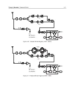
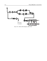
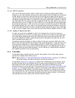
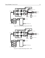
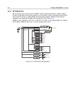
3.1.4.8 Port Expander
U703 is a port expander that is controlled by the auxiliary SPI of the Trident IC; pins A7
(ASPI_DATA), B7 (ASPI_CLK) and C6 (ACE1_GPO7). Data sent on the main SPI bus with a specific
header, tells the Trident IC to pass the data (via the auxiliary SPI lines) onto the port expander SPI
lines, pins 32 (SCLK), 33 (DIN) and 34 (CS). The port expander then translates this auxiliary SPI
data and turns on and off the select lines for the various VCOs, switches (that select the correct RF
path for either VHF, UHF or 7/800) and other logic external to the FGU.
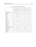
Table 3-3
below shows the
logic settings for the port expander for the various bands.
Table 3-3. Port Expander Pin Settings
VHF TX
PIN NO.
1
2
3
4
5
6
7
8
9
10
12
13
14
15
LOGIC
0
0
0
0
0
0
H
H
0
0
0
0
0
0
PIN NO.
16
17
18
19
21
22
23
24
25
26
27
28
29
30
LOGIC
0
H
0
0
0
H
H
H
0
H
0
0
0
0
VHF RX
PIN NO.
1
2
3
4
5
6
7
8
9
10
12
13
14
15
LOGIC
H
H
H
H
0
0
0
0
0
0
0
0
0
0
PIN NO.
16
17
18
19
21
22
23
24
25
26
27
28
29
30
LOGIC
0
0
0
0
0
H
0
0
0
0
0
0
0
0
700 TX
PIN NO.
1
2
3
4
5
6
7
8
9
10
12
13
14
15
LOGIC
0
0
0
0
H
0
0
0
H
0
0
0
0
0
PIN NO.
16
17
18
19
21
22
23
24
25
26
27
28
29
30
LOGIC
0
0
0
0
0
H
0
0
0
0
H
H
0
0
700 RX
PIN NO.
1
2
3
4
5
6
7
8
9
10
12
13
14
15
LOGIC
0
0
H
0
H
0
0
0
0
H
0
0
0
0
PIN NO.
16
17
18
19
21
22
23
24
25
26
27
28
29
30
LOGIC
0
0
0
0
0
H
0
0
0
0
0
0
0
H
7/800 TX
PIN NO.
1
2
3
4
5
6
7
8
9
10
12
13
14
15
LOGIC
H
0
0
0
0
H
0
0
0
0
0
0
0
0
PIN NO.
16
17
18
19
21
22
23
24
25
26
27
28
29
30
LOGIC
0
0
0
0
0
H
0
0
0
0
H
H
0
0
800 TX
PIN NO.
1
2
3
4
5
6
7
8
9
10
12
13
14
15
LOGIC
0
0
0
0
H
0
0
0
0
H
0
0
0
0
PIN NO.
16
17
18
19
21
22
23
24
25
26
27
28
29
30
LOGIC
0
0
0
0
0
H
0
0
0
0
H
H
0
0
800 RX
PIN NO.
1
2
3
4
5
6
7
8
9
10
12
13
14
15
LOGIC
0
0
H
0
H
0
0
0
H
0
0
0
0
0
PIN NO.
16
17
18
19
21
22
23
24
25
26
27
28
29
30
LOGIC
0
0
0
0
0
H
0
0
H
0
0
0
0
H
Summary of Contents for ASTRO APX 7000
Page 1: ......
Page 4: ...iv Document History Notes ...
Page 24: ...2 4 Radio Power DC Power Routing VOCON Board Notes ...
Page 98: ...3 74 Theory of Operation Global Positioning System GPS ...
Page 163: ...Troubleshooting Charts PA Failure 5 59 ...
Page 164: ...5 60 Troubleshooting Charts PA Failure ...
Page 276: ...7 58 Troubleshooting Tables List of Board and IC Signals Notes ...
Page 318: ...8 42 Schematics Boards Overlays and Parts Lists Transceiver RF Boards VHF 700 800 Notes ...
Page 380: ...8 104 Schematics Boards Overlays and Parts Lists Transceiver RF Boards UHF1 700 800 MHz Notes ...
Page 432: ...8 156 Schematics Boards Overlays and Parts Lists Transceiver RF Boards UHF1 VHF Notes ...
Page 458: ...8 182 Schematics Boards Overlays and Parts Lists Transceiver RF Boards UHF1 UHF2 Notes ...
Page 498: ...8 222 Schematics Boards Overlays and Parts Lists Transceiver RF Boards UHF2 700 800 MHz Notes ...
Page 546: ...8 270 Schematics Boards Overlays and Parts Lists Transceiver RF Boards UHF2 VHF Notes ...
Page 606: ...8 330 Schematics Boards Overlays and Parts Lists VOCON Boards Notes ...
Page 638: ...Glossary 10 Glossary Notes ...
Page 643: ......