


8-2
Schematics, Boards Overlays, and Parts Lists
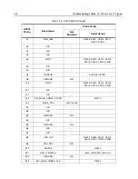
: List of VOCON Schematics and Board Overlays
8.2
List of VOCON Schematics and Board
Overlays
Figure 8-1.
List of Expansion Board Schematics and
Overlays
MNUE7367A Transmitter and Automatic Level Control Circuits
8-166
MNUE7367A Frequency Generation Unit (Synthesizer) Circuit – 1 of 2
8-167
MNUE7367A Frequency Generation Unit (VCO) Circuit – 2 of 2
8-168
MNUE7367A Mixer and IF Filter Circuits
8-169
MNUE7367A UHF1 Power Amplifier Circuit
8-170
MNUE7367A UHF2 Power Amplifier Circuit
8-171
MNUE7367A Transceiver (RF) Board Layout – Side 1
8-172
MNUE7367A Transceiver (RF) Board Layout – Side 2
8-173
UHF2 / 7/800
: MNUS4002A
MNUS4002A/E Transceiver (RF) Board Overall Circuit Schematic
8-183
MNUS4002A/E UHF2 Harmonic Filter Circuit
8-184
MNUS4002A/E 700–800 MHz Harmonic Filter Circuit
8-184
MNUS4002A/E GPS Circuit
8-185
MNUS4002A/E Miscellaneous Connector Circuit
8-186
MNUS4002A/E UHF2 Receiver Front End Circuit
8-187
MNUS4002A/E 700–800 MHz Receiver Front End Circuit
8-188
MNUS4002A Receiver Back End Circuit
8-189
MNUS4002A/E DC Power Circuit
8-191
MNUS4002A/E Transmitter and Automatic Level Control Circuits
8-192
MNUS4002A/E Frequency Generation Unit (Synthesizer) Circuit – 1 of 2
8-193
MNUS4002A/E Frequency Generation Unit (VCO) Circuit – 2 of 2
8-194
MNUS4002A/E Mixer and IF Filter Circuits
8-195
MNUS4002A/E UHF2 Power Amplifier Circuit
8-196
MNUS4002A/E 700–800 MHz Power Amplifier Circuit
8-197
MNUS4002A/E Transceiver (RF) Board Layout – Side 1
8-198
MNUS4002A/ETransceiver (RF) Board Layout – Side 2
8-199
UHF2/ VHF
: MNUT4004A/C/E
MNUT4004A/C/E Transceiver (RF) Board Overall Circuit Schematic
8-223
MNUT4004A/C/E UHF2 Harmonic Filter Circuit
8-224
MNUT4004A/C/E VHF MHz Harmonic Filter Circuit
8-224
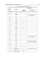
Table 8-1. Transceiver Schematics and Board Overlays (Continued)
Transceiver Board Schematic/Board Layout
Page
No.
MNUT4004A/C/EGPS Circuit
8-225
MNUT4004A/C/E Miscellaneous Connector Circuit
8-226
MNUT4004A/C/E UHF2 Receiver Front End Circuit
8-227
MNUT4004A/C/E VHF Receiver Front End Circuit
8-228
MNUT4004A/C Receiver Back End Circuit
8-229
MNUT4004A/C/E DC Power Circuit
8-231
MNUT4004A/C/E Frequency Generation Unit (Synthesizer) Circuit – 1 of
2
8-233
MNUT4004A/C/E Frequency Generation Unit (VCO) Circuit – 2 of 2
8-234
MNUT4004A/C/E Mixer and IF Filter Circuits
8-235
MNUT4004A UHF2 Power Amplifier Circuit
8-236
MNUT4004C/E UHF2 Power Amplifier Circuit
8-237
MNUT4004A/C/E VHF Power Amplifier Circuit
8-238
MNUT4004A/C/E Transceiver (RF) Board Layout – Side 1
8-239
MNUT4004A/C/E T Transceiver (RF) Board Layout – Side 2
8-240
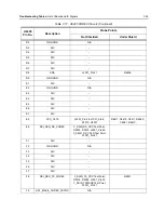
Table 8-2. List of VOCON Schematics and Board Overlays
VOCON Board Schematic/Board Layout
Page
No.
MNCN6200A/MNCN6201A/MNCN6202A/MNCN6203A VOCON Board
Overall Schematic
8-271
MNCN6200A/MNCN6201A/MNCN6202A/MNCN6203A VOCON CID,
Controls and JTAG Schematics
8-272
MNCN6200A/MNCN6201A VOCON LCD and Connector Circuits
8-273
MNCN6202A/MNCN6203A VOCON LCD and Connector Circuits
8-274
MNCN6200A VOCON Lighting Controller Circuits
8-275
MNCN6201A VOCON Lighting Controller Circuits
8-276
MNCN6202A VOCON Lighting Controller Circuits
8-277
MNCN6203A VOCON Lighting Controller Circuits
8-278
MNCN6200A/MNCN6201A VOCON Memory Interface Circuits
8-279
Table 8-1. Transceiver Schematics and Board Overlays (Continued)
Transceiver Board Schematic/Board Layout
Page
No.
MNCN6202A/MNCN6203A VOCON Memory Interface Circuits
8-280
MNCN6200A/MNCN6201A/MNCN6202A/MNCN6203A VOCON
Expansion Interface Circuits
8-281
MNCN6200A/MNCN6201A VOCON Codec and Mako Audio Circuits
8-282
MNCN6202A/MNCN6203A VOCON Codec and Mako Audio Circuits
8-283
MNCN6200A/MNCN6201A/MNCN6202A/MNCN6203A VOCON Secure
Circuits
8-284
MNCN6200A/MNCN6201A/MNCN6202A/MNCN6203A Option Board
Interface Circuit
8-285
MNCN6200A/MNCN6201A/MNCN6202A/MNCN6203A VOCON CPLD
Circuit
8-286
MNCN6200A/MNCN6201A/MNCN6202A/MNCN6203A VOCON OMAP
User Interface Circuits
8-287
MNCN6200A/MNCN6201A/MNCN6202A/MNCN6203A VOCON Power
Circuits – 1 of 2
8-288
MNCN6200A/MNCN6201A VOCON Power Circuits – 2 of 2
8-289
MNCN6202A/MNCN6203A VOCON Power Circuits – 2 of 2
8-290
MNCN6200A/MNCN6201A/MNCN6202A/MNCN6203A VOCON Serial
Interface Circuit
8-291
MNCN6200A/MNCN6201A/MNCN6202A/MNCN6203A VOCON RF
Interface Circuit
8-292
MNCN6200A/MNCN6201A VOCON Board Layout – Side 1
8-293
MNCN6200A/MNCN6201A VOCON Board Layout – Side 2
8-294
MNCN6202A/ MNCN6203A VOCON Board Layout – Side 1
8-295
MNCN6202A/ MNCN6203A VOCON Board Layout – Side 2
8-296
Table 8-3. List of Expansion Board Schematics and Board Overlays
Expansion Board Schematic
Page No.
MHLN6977A Expansion Board Overall Circuit Schematic
8-331
MHLN6977B Expansion Board Overall Circuit Schematic
8-332
MHLN7035A Expansion Board Overall Circuit Schematic
8-333
MHLN6977A/B GPS Circuit
8-334
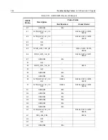
Table 8-2. List of VOCON Schematics and Board Overlays (Continued)
VOCON Board Schematic/Board Layout
Page
No.
Summary of Contents for ASTRO APX 7000
Page 1: ......
Page 4: ...iv Document History Notes ...
Page 24: ...2 4 Radio Power DC Power Routing VOCON Board Notes ...
Page 98: ...3 74 Theory of Operation Global Positioning System GPS ...
Page 163: ...Troubleshooting Charts PA Failure 5 59 ...
Page 164: ...5 60 Troubleshooting Charts PA Failure ...
Page 276: ...7 58 Troubleshooting Tables List of Board and IC Signals Notes ...
Page 318: ...8 42 Schematics Boards Overlays and Parts Lists Transceiver RF Boards VHF 700 800 Notes ...
Page 380: ...8 104 Schematics Boards Overlays and Parts Lists Transceiver RF Boards UHF1 700 800 MHz Notes ...
Page 432: ...8 156 Schematics Boards Overlays and Parts Lists Transceiver RF Boards UHF1 VHF Notes ...
Page 458: ...8 182 Schematics Boards Overlays and Parts Lists Transceiver RF Boards UHF1 UHF2 Notes ...
Page 498: ...8 222 Schematics Boards Overlays and Parts Lists Transceiver RF Boards UHF2 700 800 MHz Notes ...
Page 546: ...8 270 Schematics Boards Overlays and Parts Lists Transceiver RF Boards UHF2 VHF Notes ...
Page 606: ...8 330 Schematics Boards Overlays and Parts Lists VOCON Boards Notes ...
Page 638: ...Glossary 10 Glossary Notes ...
Page 643: ......