5-52
Troubleshooting Charts:
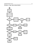
PA Failure
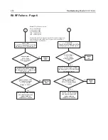
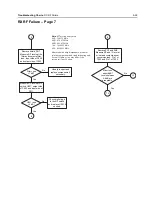
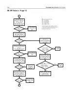
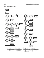
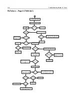
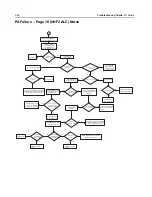
PA Failure – Page 4 (Multi Switch)
No
No
Yes
Yes
No
No
Yes
Yes
No
No
Yes
Yes
No
No
Yes
Yes
No
No
Yes
Yes
Yes
No
No
No
shorted?
13
14
15
VHF TX (VHF / 7/800)
UHF1 TX (UHF1 / 7/800)
UHF1 TX (UHF1 / VHF)
VHF TX (UHF1 / VHF)
0
1
1
7/800 TX (VHF / 7/800)
7/800 TX (UHF1 / 7/800)
1
1
1
0
1
1
RX
1
1
1
1
1
1
0
1
1
UHF2 TX (UHF2 / 7/800)
UHF2 TX (UHF2 / VHF)
VHF TX (UHF2 / VHF)
UHF1 TX (UHF1 / UHF2)
UHF2 TX (UHF1 / UHF2)
7/800 TX (UHF2 / 7/800)
0
1
1
1
1
1
1
1
1
0
1
1
1
0
0
1
1
1
0
1
1
No
No
No
Yes
Pin
Yes
Yes
Yes
Yes
Is supply to
U1102 pin 12
near 3.3 V?
Is logic correct?
Is the pin
Are the pins
shorted?
4
Is resistance
less than 10
Ohms?
Were any pins
shorted?
Are any of the
pins shorted?
Is resistance
less than 10
Ohms?
Are any of the
pins shorted?
Is resistance
less than 10
Ohms?
Are any of the
pins shorted?
Were all
resistances
correct?
Is resistance
greater than 20K
Ohms?
Are any of the
pins shorted?
Is resistance
greater than 20K
Ohms?
Are any of the
pins shorted?
Lift shield SH13 and
check switch U1102
for functionality.
In RX mode, measure
resistance on U1102
from pin 9 to pin 28.
In RX mode, measure
resistance on U1102
from pin 3 to 28 and
from pin 22 to 28.
Clear short, or
replace U1102.
Clear short, or
replace U1102.
Clear short, or
replace U1102.
Clear short, or
replace U1102.
Clear short, or
replace U1102.
Clear short, or
replace U1102.
Clear short, or
replace U1102.
Remove ferrite bead E1101
to disable the PA's .
In VHF TX mode, measure
resistance on U1102 from
pin 3 to pin 28.
In 7/800 TX mode,
measure resistance
on U1102 from pin 22
to pin 28.
In either TX mode,
measure resistance
on U1102 from pin 9
to 28.
Check for solder
shorts on the RF pins
1,2,23,24, and 28.
If all else is OK, and
resistance is still high,
then replace U1102
and re-measure
power.
Clear short, or
replace U1102.
Verify logic to pin 13, 14 and
15 of U1102, using the table
to the left for reference. Logic
high ~ 3 V, and logic low ~ 0 V.
Verify voltage
divider at R1183
and R1184 under
sheild SH13.
This logic is controlled by several
IC's that cannot be probed
because of the package type.
Check U1116, U1117, U1118,
and U1123 for any issues and
replace as necessary. If no
trouble found see FGU trouble
shooting charts for further TX
signaling information.
Check pins 8,
9, 27, 28 and
29 for solder
shorts.
Check pins 2,
3, 4, 21, 22, 23,
27, 28 and 29
for solder shorts.
Check pins 2, 3
and 4 for solder
shorts.
Check pins 21,
22 and 23 for
solder shorts.
Check pins 8,
9, 27, 28 and
29 for solder
shorts.
U1102 is functional,
follow PA specific
charts 1 or 2.
Check pin 12
for solder
shorts.
Check pins 13, 14
and 15 for solder
shorts.
Summary of Contents for ASTRO APX 7000
Page 1: ......
Page 4: ...iv Document History Notes ...
Page 24: ...2 4 Radio Power DC Power Routing VOCON Board Notes ...
Page 98: ...3 74 Theory of Operation Global Positioning System GPS ...
Page 163: ...Troubleshooting Charts PA Failure 5 59 ...
Page 164: ...5 60 Troubleshooting Charts PA Failure ...
Page 276: ...7 58 Troubleshooting Tables List of Board and IC Signals Notes ...
Page 318: ...8 42 Schematics Boards Overlays and Parts Lists Transceiver RF Boards VHF 700 800 Notes ...
Page 380: ...8 104 Schematics Boards Overlays and Parts Lists Transceiver RF Boards UHF1 700 800 MHz Notes ...
Page 432: ...8 156 Schematics Boards Overlays and Parts Lists Transceiver RF Boards UHF1 VHF Notes ...
Page 458: ...8 182 Schematics Boards Overlays and Parts Lists Transceiver RF Boards UHF1 UHF2 Notes ...
Page 498: ...8 222 Schematics Boards Overlays and Parts Lists Transceiver RF Boards UHF2 700 800 MHz Notes ...
Page 546: ...8 270 Schematics Boards Overlays and Parts Lists Transceiver RF Boards UHF2 VHF Notes ...
Page 606: ...8 330 Schematics Boards Overlays and Parts Lists VOCON Boards Notes ...
Page 638: ...Glossary 10 Glossary Notes ...
Page 643: ......

