18
GB
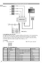
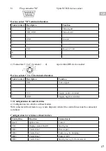
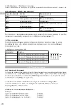
b) Configuration for vehicles with trailers
With vehicles with trailers the control lines must be connected as follows:
Configuration for vehicles with trailers
Control line
Function
Connection to
Quad
Split-screen
Contact
POC
Display contact On/Off
Switch plus
SEL1
Control line 1
Reverse gear
SEL2
Control line 2
Contact trailer camera
SEL3
Control line 3
Contact
SEL4
Control line 4
Switch plus (e.g for front camera)
The system automatically switches to the trailer camera (camera 2) if this is connected to C2 by
mneas of a suitable cable (e.g. MK84.xx).
3.4 Start-up
Before putting the camera system into operation, the safety regulations outlined under point 2
must be observed. The remaining settings (e.g. image mirroring) should be set up as follows:
a) Setting the DIP switches
Switch
Function
1
Camera C4 image mirroring, left/right
2
Camera C3 image mirroring, left/right
3
Camera C2 image mirroring, left/right
4
Camera C1 image mirroring, left/right
4.0 Operation
4.1 Operation of the device
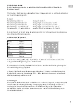
The MB1405-Quad is switched on by applying the supply voltage. A display can be switched
on by applying the supply voltage to the "POC" line. The control lines for the MB1405-Quad
are activated using NO contacts (see Fig. 3.1-1).
The appropriate camera is selected via the corresponding control line. When selecting a camera
via the control lines, the camera input with the lowest number has the highest priority.
4.2 Single mode
Example:
Control lines 1 and 4 activated:
Display: camera 1
Control lines 3 and 4 activated:
Display: camera 3
Control lines 2, 3 and 4 activated:
Display: camera 2
Summary of Contents for 406 0172 003
Page 11: ...11 DE Notes...
Page 21: ...21 GB Notes...
Page 31: ...31 FR Notes...
Page 41: ...TR Notes...
Page 42: ...Notes...
Page 43: ...Notes...


