16
GB
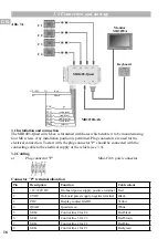
3.1 Installation and connection
The MB1405-Quad switch box is furnished with holes which enable it to be mounted using
four M4 screws. Any installation position is permitted. Plug connectors are used for the
electrical connection. To start with, the plug connector "P" should be connected with the
connecting cable to the electrical supply of the vehicle (see 3.3).
3.0 Connection and start-up
C1
C2
C3
C4
Monitor
MD3070A
Keyboard
MB1405-Quad
+12/+24V
0V
Red
Black
POC
SEL1
SEL2
SEL3
SEL4
Quad
ge
(red/green)
(red/blue)
(red/brown)
(red/black)
(white)
MD3072B-AK
3A
Abb. 3.1
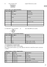
3.2 Cabling
a)
Plug connector "P"
Mini-Fit (8 pole) connector
Connector "P" terminal allocation
Pin
Description
Function
Cable colour
1
+12/+24V DC
On-board power supply, positive terminal Red
2
0V DC
On-board power supply, negative terminal Black
3
POC
Display contact On/Off
Yellow
4
QUAD
Quad screen
White
5
SEL4
Control line 4 for C4
Red/black
6
SEL3
Control line 3 for C3
Red/brown
7
SEL2
Control line 2 for C2
Red/blue
8
SEL1
Control line 1 for C1
Red/green
Summary of Contents for 406 0172 003
Page 11: ...11 DE Notes...
Page 21: ...21 GB Notes...
Page 31: ...31 FR Notes...
Page 41: ...TR Notes...
Page 42: ...Notes...
Page 43: ...Notes...

