


General Information
ProStar Operator’s Manual
17
16
2.0
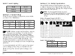
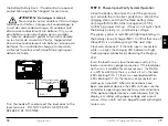
Figure 2.1. ProStar Features
Figure 2.3. Removable
Terminal Cover
2.3 Features
The features of the ProStar are shown in Figures 2-1,
2.2 and 2.3 below. An explanation of each feature
follows.
12
12
12
10
4
2
12
3
1
8
9
5
11
6
7
13
14
15
Figure 2.2. Non-Metered
Unit Push-Button
1 - Charging Status / Error LED
Shows charging current and error condition statuses.
2 - Heatsink
Aluminum heatsink (underneath) to dissipate
controller heat (the ProStar is 100% passively cooled
for reliability)
3 - Meter Display (optional)
Digital LCD monitoring and programming display
4 - Battery Status / Fault LED Indicators
Three state of charge (SOC) LED indicators show
charging status and controller faults
5 - Solar Positive and Negative Terminals
Power connections for Solar (+) and (-) cable
terminations
6 - Battery Positive and Negative Terminals
Power connections for Battery (+) and (-) cable
terminations
7 - Load Positive and Negative Terminals
Power connections for Load (+) and (-) cable
terminations
8 - Local Temperature Sensor
Compensates charging based on ambient
temperature, in absence of Remote Temperature
Sensor
9 - Meter Directional Buttons
Used to navigate throughout the meter map
10 - DIP Switches
Eight (8) settings switches to configure operation of
the ProStar


