


Installation
ProStar Operator’s Manual
23
22
3.0
• The ProStar prevents reverse current leakage at
night, so a blocking diode is not required in the
system.
• The ProStar is designed to regulate ONLY solar
(photovoltaic) power. Connection to any other type
of power source e.g. wind turbine or generator may
void the warranty. However, other power sources
may be connected directly to the battery.
• The connector terminals will accept a maximum
wire size of AWG #6 / 16 mm2 (solid/multi-strand)
or #8 AWG / 10 mm
2
(fine strand). Use an insulated
flathead screwdriver, and torque tightly up to 35
in-lb.
• Stranded wires to be connected to the ProStar
terminals should be prepared first with e.g.
clamped copper heads, etc. to avoid the
possibility of conductor strands coming free out of
the connection screw, and possible contact with the
metal enclosure.
WARNING:
Solar and battery fuses or DC
breakers are required in the system. These
protection devices are external to the ProStar
controller, and must be a maximum of 20 Amps for the
ProStar-15/M, and 50 Amps for the ProStar-30/M.
AVERTISSEMENT :
Fusibles solaires et de
batterie ou CC des disjoncteurs sont néces-
saires dans le système. Ces dispositifs de protection
sont externes au contrôleur ProStar et doivent être au
maximum de 20 A pour le ProStar-15 / M et de 50 A
pour le ProStar-30 / M.
WARNING:
All breakers must be properly
rated for wire ampacity, which may require less
than the maximum breaker sizes referenced above.
AVERTISSEMENT :
Tous les disjoncteurs doi
vent être correctement dimensionnés pour
l'intensité du fil, ce qui peut nécessiter moins que
les tailles de disjoncteur maximales mentionnées
ci-dessus.
WARNING:
Minimum over-current
protection device interrupt ratings must be
2000A for 12V systems, and 4000A for 24V systems.
AVERTISSEMENT :
Surintensité minimale
Les valeurs nominales d'interruption des dis-
positifs de protection doivent être de 2 000 A pour les
systèmes 12 V et de 4 000 A pour les systèmes 24 V.
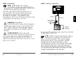
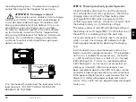
NOTE:
Carefully observe the LEDs after
each connection. The LEDs will indicate
proper polarity, and a secure co nnection.
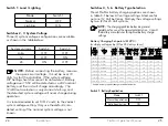
3.2 Configuration
The DIP switch block shown in Figure 3.1 below is
used to set the operating parameters for the ProStar.
Figure 3.1. DIP Switch Block to set charging parameters


