


193
67: Bacnet communication fault (E-BAC)
68: DeviceNet communication fault (E-DEV)
69: Master-slave synchronous CAN slave fault (S-Err)
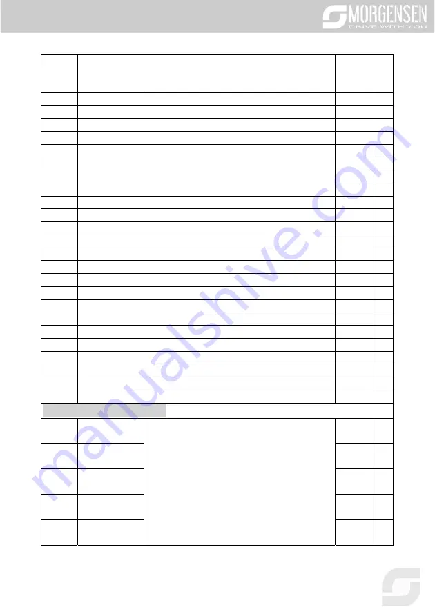
P07.33 Running frequency of present fault
0.00Hz
●
P07.34 Ramps reference frequency of present fault
0.00Hz
●
P07.35 Output voltage of present fault
0V
●
P07.36 Output current of present fault
0.0A
●
P07.37 Bus voltage of present fault
0.0V
●
P07.38 Max. temperature of present fault
0.0°C
●
P07.39 Input terminal state of present fault
0
●
P07.40 Output terminal state of present fault
0
●
P07.41 Running frequency of the last fault
0.00Hz
●
P07.42 Ramps reference frequency of the last fault
0.00Hz
●
P07.43 Output voltage of the last fault
0V
●
P07.44 Output current of the last fault
0.0A
●
P07.45 Bus voltage of the last fault
0.0V
●
P07.46 Max. temperature of the last fault
0.0°C
●
P07.47 Input terminal state of the last fault
0
●
P07.48 Output terminal state of the last fault
0
●
P07.49 Running frequency of the last but one fault
0.00Hz
●
P07.50 Ramps reference frequency of the last but one fault
0.00Hz
●
P07.51 Output voltage of the last but one fault
0V
●
P07.52 Output current of the last but one fault
0.0A
●
P07.53 Bus voltage of the last but one fault
0.0V
●
P07.54 Max. temperature of the last but one fault
0.0°C
●
P07.55 Input terminal state of the last but one fault
0
●
P07.56 Output terminal state of the last but one fault
0
●
P08 group Enhanced functions
P08.00
Acceleration
time 2
See P00.11 and P00.12 for detailed definitions.
MSI350 series inverter defines four groups of
acceleration/deceleration time, which can be selected
by multi-function digital input terminal (P05 group). The
acceleration/deceleration time of the inverter is the first
group by default.
Setting range: 0.0–3600.0s
Depend
on model
○
P08.01
Deceleration
time 2
Depend
on model
○
P08.02
Acceleration
time 3
Depend
on model
○
P08.03
Deceleration
time 3
Depend
on model
○
P08.04
Acceleration
time 4
Depend
on model
○
Summary of Contents for MSI350 Series
Page 1: ...MSI350 SERIES INVERTER USER MANUAL...
Page 2: ...2...
Page 34: ...34 4 2 6 Vertical installation Fig 4 5 Vertical installation...
Page 38: ...38 Fig 4 10 3PH 380V 30 37kW Fig 4 11 3PH 380V 45 110kW Fig 4 12 660V 22 45kW...
Page 39: ...39 Fig 4 13 660V 55 132kW Fig 4 14 380V 132 200kW and 660V 160 220kW...
Page 40: ...40 Fig 4 15 380V 220 315kW and 660V 250 355kW...
Page 71: ...71...
Page 83: ...83 When selecting customized V F curve function users can set the reference channels and...
Page 90: ...90...
Page 96: ...96...
Page 101: ...101...
Page 147: ...147...
Page 260: ...260 7 6 Analysis on common faults 7 6 1 Motor fails to work...
Page 261: ...261 7 6 2 Motor vibrates...
Page 262: ...262 7 6 3 Overvoltage...
Page 263: ...263 7 6 4 Undervoltage...
Page 264: ...264 7 6 5 Unusual heating of motor...
Page 265: ...265 7 6 6 Inverter overheating...
Page 266: ...266 7 6 7 Motor stalls during ACC...
Page 267: ...267 7 6 8 Overcurrent...
Page 336: ...336 A 6 5 PROFINET communication card EC TX509...
Page 380: ...380...
Page 386: ...386...
Page 387: ...387...
Page 388: ...388...