background image

Page 15

SYSTEM

Perforating

Once the machine is set-

Note
Perforating and creasing can be carried out simultaneously. However, if any
adjustment is made to the roller tilt mechanism in order to compensate for the
perforation line being ’out of square’, this may effect the accuracy of the crease. If
this occurs creasing and perforating must be carried out as separate operations.

The components and tools required to install the perforator are contained in the despatch
kit supplied with the machine, they are listed below.

1 off Set of standard perforation ‘56 tooth’ blades.
1 off Set of standard hardened anvils.
1 off Perforator stripper.
1 off Scoring wheel
1 off 3mm bondhus wrench / allen key
1 off 2mm bondhus wrench / allen key

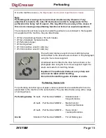
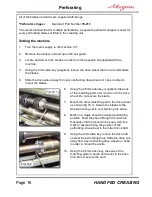
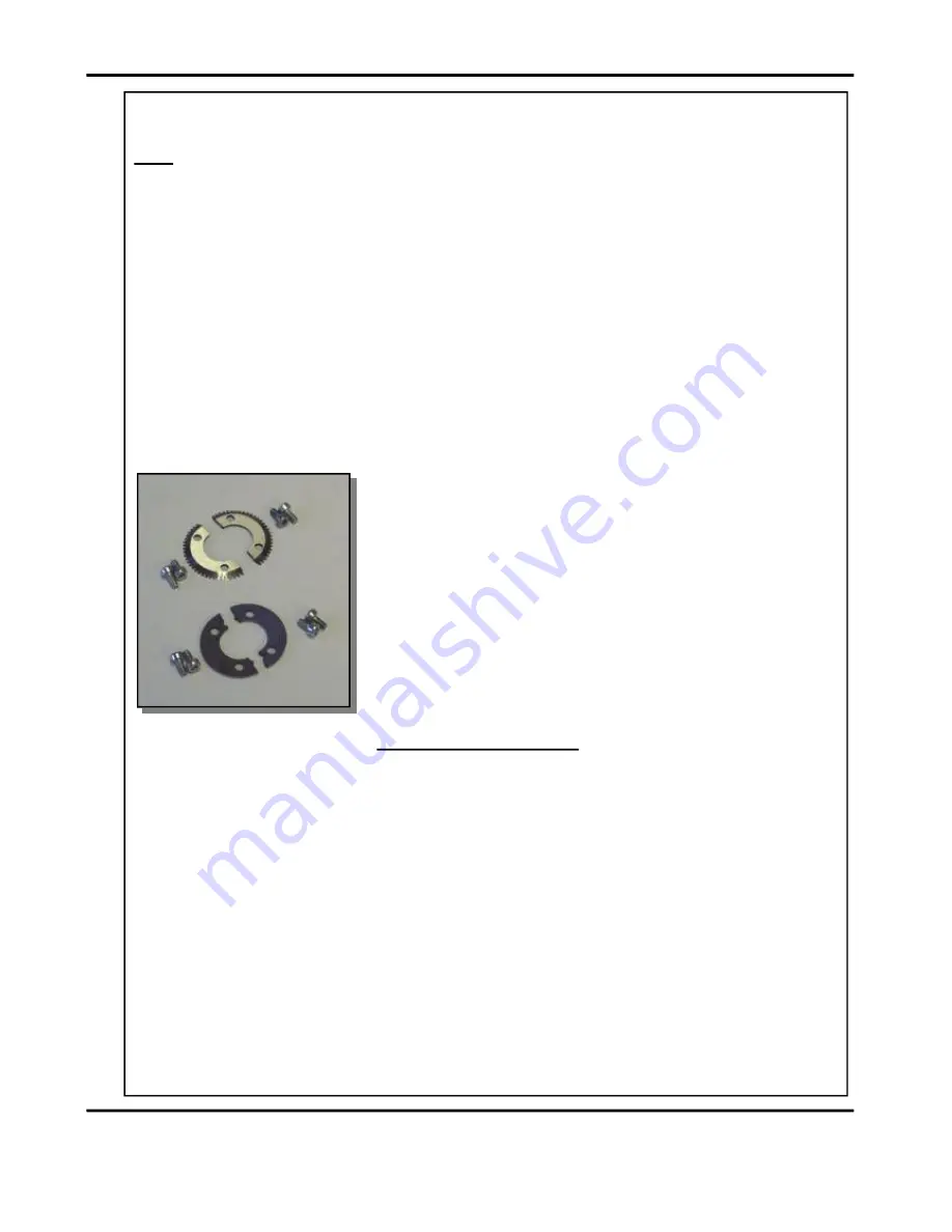
The perforator blades are split into two matching halves
and are fitted to the drive wheels as shown in the photograph
using the four screws supplied.

A hardened anvil is fitted to the drive hub as shown in the
photograph also using the four screws supplied. Again the
anvils are made from matching halves.

Important: The perforator blades are very sharp and
care must be taken whilst handling.
Do not mix the matching pairs of blades or anvils.

Perforating ‘Spares’ kits

For perforating and other types of paper, various spares kits are available which can be
assembled to the machine in the same fashion. They are listed below along with a range
of scoring wheels,

Perforating blades

56 teeth

Part Number

1-99-41

Standard stock /
fine perforations.

28 teeth

Part Number

1-99-12

Medium stock /
medium perforations.

20 teeth

Part Number

1-99-10

Heavy stock /
coarse perforations.

Anvils

Standard Part Number

1-99-35

For all blade types

up, the Digicreaser can be used to perforate or crease.

DigiCreaser

Summary of Contents for DigiCreaser

Page 1: ...ISSUE 6 OCTOBER 2012 HAND FED DOCUMENT CREASING MACHINE OPERATORS MANUAL 70 087 DigiCreaser Website www morgana co uk Morgana Systems Limited United Kingdom Telephone 01908 608888 Facsimile 01908 692399 ...

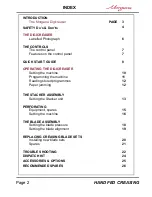
Page 2: ... jamming 12 THE STACKER ASSEMBLY Setting the Stacker unit 13 PERFORATING Equipment spares 15 Setting the machine 16 THE BLADE ASSEMBLY Setting the blade pressure 18 Setting the blade alignment 19 REPLACING CREASING BLADE SETS Installing new blade sets 20 Spares 21 TROUBLE SHOOTING 22 INDEX DISPATCH KIT 24 ACCESSORIES OPTIONS 25 RECOMMENDED SPARES 26 SAFETY Do s Don ts 4 OPERATING THE DIGICREASER T...

Page 3: ...using the controls on the front panel A minimum distance between creases is 0 1mm programmed creasing operations The blade and anvil are mechanically controlled over their entire length and can be adjusted to accommodate various weights of media The Digicreaser has up to nine available memory addresses for The Digicreaser is capable of creasing sheet sizes to a maximum of The Morgana Digicreaser i...

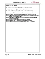
Page 4: ...tall the machine in an unstable place such that it tilts or shakes Do not unplug the plug or unplug the power cord from the outlet with a wet hand this can cause an electric shock Do not unscrew and remove any covers from the machine as it can cause an electric shock or injury Do read this operator manual fully before operating the machine Do not place receptacles containing liquids on any surface...

Page 5: ...Page 5 SYSTEM BLANK PAGE DigiCreaser ...

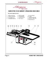
Page 6: ...1 Roller tilt handle 6 2 Stacker assembly 7 Adjustable side lay Exit Guard 3 8 Back stop RH 4 The display unit 9 Fixed side lay 5 10 Roller tilt knob Fuses Control Panel 13 Back Stop LH HAND FED CREASING 11 12 Stacker Guide RH Stacker Guide LH DIGICREASER Digicreaser ...

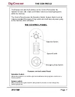
Page 7: ...ol Panel allow the operator to read edit create and initiate numerous creasing programs within the memory THE CONTROL PANEL System Switch Emergency Stop Switch Selection Switch Features on the Control Panel Selection Switch Allows the operator to scroll through stored addresses and programs and to set a crease position System switch When activated the system switch will operate the motors in order...

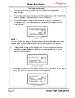
Page 8: ...y denote the direction in which the selection switch must be moved in order to access the various sub menus NOTE 2 HAND FED CREASING 4 Following the arrows on the display unit move the selection switch to the right to select i e Setting the crease positions a typical Setup display is shown below 5 Following the arrows on the display unit move the selection switch down to set the creases The 1st Cr...

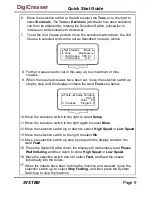
Page 9: ...own the display will momentarily read Please Move the selection switch down to select and feed the sheets Feed creases Wait Initiating High Speed Low Speed and then return to show or 17 individually into the rollers When the sheets have been fed into the machine and creased move the selection switch up to select and then press the System Stop Feeding Switch up to stop the machine 10 11 Move the se...

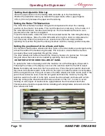
Page 10: ...rranged evenly across the width of the media being creased This is done to ensure that the media is accurately driven and supported through the rollers The drive wheels and hubs are fixed to the rollers by means of a grub screw To locate this grub screw the rollers can be rotated by operating the motor manually DO NOT ROTATE THE DRIVE ROLLERS BY HAND To operate the motors manually switch the machi...

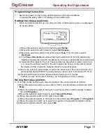
Page 11: ... the selected program number vii Move the selection switch up to select Ok i Move the selection switch to the right to select Setup ii Move the selection switch down to select Set Creases iii Move the selection switch to the left to select or to the right to select Tens Decimals iv The or whichever has been selected can then be adjusted by Tens Decimals Rotating the Selection Switch clockwise to i...

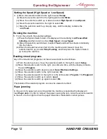
Page 12: ...election switch to the right or to the left to select to Program 1 Program 9 vi Move the selection switch up to select Load vii Move the selection switch up again to select Ok The details of the selected program can now be viewed or edited Paper jamming In the event of a paper jam occurring whilst the machine is operating the display will read Paper Jam In order to remove the paper causing the jam...

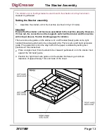
Page 13: ...r unit a left handed fixed guide and a right guide The guides will control the way in which the paper is collated by setting their positions on the stacker bed 2 3 Place a single sheet from the stack to be creased perforated on to the stacker bed against the left hand guide Position the right hand side guide on to the stacker bed leaving a minimum clearance of approximately 1mm each side of the sh...

Page 14: ...st the sheet is between the two guides on the stacker bed set the distance between the top of the sheet and the backstop flanges to approximately 5mm For shorter sheets the back stop can be used as shown in FIG 13 1 to adjust the position of the paper stack ...

Page 15: ... into two matching halves and are fitted to the drive wheels as shown in the photograph using the four screws supplied A hardened anvil is fitted to the drive hub as shown in the photograph also using the four screws supplied Again the anvils are made from matching halves Important The perforator blades are very sharp and care must be taken whilst handling Do not mix the matching pairs of blades o...

Page 16: ...rder to mount the blades 6 Using the 2 5mm allen key supplied take one of the matching pairs and mount on to the drive wheel Do not secure the blade 7 Mount the other matching pair to the drive wheel as shown fig 16 1 Secure the blades to the wheel ensuring not to over tighten grub screw 8 Mark on a single sheet the desired perforating position Feed the sheet through the machine manually until the...

Page 17: ...ive wheel and blade as shown 15 Operate the machine and test the perforations for form It is important that the drive hubs are arranged evenly across the width of the paper in order to reduce the risk of jamming For multiple perforations repeat the above procedure Always remove blades and anvils once the perforating operation has been completed to avoid marking on digital or delicate media 5 2 1 3...

Page 18: ...ht the machine will activate and the blade will move to top dead center The display will now read Blade is moving to TOP DEAD CENTER Blade Pressure May Now Be Adjusted See and then change to read Operators Manual 2 Raise the exit guard 3 Using a 6mm allen key unlock the shoulder bolts labelled with scale transfer positioned at each end of the creasing blade 4 Turn the adjustment cam to adjust the ...

Page 19: ...ead type locking screws located on the front face at both ends of the blade anvil as shown below 4 Using a 4mm allen key locate the two front or back alignment screws in the side frame in order to adjust the blade anvil 5 The upper screw of the two will adjust the upper blade anvil whereas the lower screw will adjust the lower blade anvil both in very small increments 6 In order to obtain the requ...

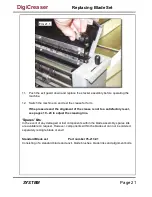
Page 20: ...Slide the adjustment links away from the dowels located in the ends of the blades anvils as shown in the photograph left 7 Place the new blade set into position Check that the eccentric shoulder bolts on the link plates have been positioned as shown in fig 20 1 8 Upper blade anvil only Slide the adjustment links onto the dowels 9 Slide the new blade set into the slots of the creasing unit as shown...

Page 21: ...evel see pages 19 20 to adjust the creasing line Spares kits In the event of any damaged or lost components within the blade assembly spares kits are available on request However components within the blade set can not be ordered separately ie single blade or anvil Standard Blade set Part number 76 213 01 Consisting of a standard blade and anvil blade brushes blade links and alignment bolts FIG 21...

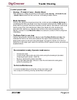
Page 22: ...down Check that the stacker unit is located correctly and has not been disconnected from the magnetic switch Check that the lower blade anvil is connecting to the home switch mounted below the lower blade anvil Paper not feeding Ensure that the adjustable side lay is not pressed against the sheet of paper On digital media the feeding performance may be improved if the leading edge of the stack is ...

Page 23: ...ntact a Service Engineer Blade Not Home immediately The Paper Path is not clear If before operating the machine the display reads this The Paper Path is not clear indicates that there is an obstruction between the upper sensor assembly and the paper guide sensor as shown in the photograph on page 22 If there is no obvious obstruction in the paper path switch the machine off and repeat the same pro...

Page 24: ...m 620 020 HEXAGON BALL DRIVER 2 5mm 7 403 01 030 006 409 01 040 004 12 SCREW SOCKET CAP HEAD M3 x 6 LG 1 SCREW SKT SET FLAT PT M4 x 4 LG 1 15 70 055 01 1 BLADE EXTRACTION TOOL OP SIDE 16 70 055 02 1 BLADE EXTRACTION TOOL LAY SIDE 17 08 041 02 1 SLITTING ANVIL UNDERSIZE 08 066 1 SLITTER PERF BLADE 28T 18 624 017 3 SLITTER SCORER PK STYLE 0212 40X40X20 WARNING THE BLADES FOR ANVIL AND PERFORATING SE...

Page 25: ... fitted by your dealer You should not attempt to fit options as specialist tools and knowledge are required May be obtained from ITEM PART NUMBER DESCRIPTION 1 99 10 PERFORATING BLADE SET 20T Card 1 1 99 12 PERFORATING BLADE SET 28T Single sheets 2 1 99 41 PERFORATING BLADE SET 56T Fine perforations 3 1 99 35 ANVIL SET USED WITH ABOVE BLADE SETS 4 7 05 14 FLOOR STANDING BASE 5 DigiCreaser ...

Page 26: ...BELT 160XL 607 048 TIMING BELT TWIN GRIP 200 DXL 050 608 019 SHOULDER BOLT 76 082 PERFORATOR DRIVE HUB ASSEMBLY 76 083 PERFORATOR DRIVE WHEEL 75 210 05 LCD DISPLAY UNIT 4 x 20 AND LEAD ASSEMBLY 144 04 04 JOYSTICK AND LEAD ASSEMBLY 655 016 PSU SWITCH MODE 48V 613 053 FAN 119mm 76 175 01 76 177 01 76 019 03 78 013 INPUT ROLLER Lower INPUT ROLLER Upper OUTPUT SHAFT PERFORATOR STRIPPER ASSEMBLY 613 35...

Page 27: ... The items listed above represent parts which are subject to wear loss or accidental damage and is included for your guidance only Replacement of parts fitted to your machine require specialist knowledge and should therefore be entrusted to your dealer DigiCreaser ...

Page 28: ...tion of this symbol on your equipment is confirmation that you should not dispose of the equipment in the normal household waste stream In accordance with European legislation end of life electrical and electronic equipment subject to disposal must be segregated from household waste Private households within EU Member States may return used electrical and electronic equipment to designated collect...

Page 29: ...Page 29 SYSTEM DigiCreaser ...

Reviews: