background image

 
       Manual Part No:   932971-01               MD Gas Convection Oven 

    Page 24 of 32 

       Manual Rev No: 1 


Service and Maintenance (cont.) 


Fault Finding. 
 

FAULT POSSIBLE 

CAUSE 

REMEDY 

Poor or broken earth wire.  Polarity 
Of live and neutral incorrect 

Repair poor or broken wire 
Connection.  Ensure that live and 
Neutral connections are correct 

PILOT LIGHTS 
MOMENTARILY 
AND ELECTRODE 
CONTINUES TO 
SPARK UNTIL UNIT 
SHUTS DOWN 

The pilot flame is too low in height 
or it is burning in an unstable 
condition 

Check pilot injector size.  Clean 
Injector and pilot assembly if 
Required.  Check gas pressure 

Failed 5 amp fuse, located at the 
rear of oven.  Check to see if oven 
Interior lamp is alight. 

Check fuse for continuity.  If it has 
failed check all possible reasons 
For failure.  Rectify fault before 
replacing fuse. 

Door micro-switch, mounted on 
rear panel, is not operating or 
broken. 

Possible misalignment between 
Door actuating rod and the micro- 
Switch actuating arm.  Adjust to 
obtain correct alignment if 
required or replace switch if 
broken. 

Failed Air Pressure Switch giving no 
output feed to Full sequence 
Control Unit 

Check output from Air Pressure 
Switch.  Replace if faulty. 

Failed Capacitor 

Check capacitor.  Replace if 
necessary. 

FAN NOT ROTATING 
WITH OVEN 
SWITCHED ON AND  
DOOR CLOSED 

Failed Motor 

Check supply to Motor.  Of supply 
to Motor is OK replace Motor. 

Thermostat not turned on or oven 
up to temperature. 

Turn on thermostat 

Main burner solenoid coil has failed  Replace coil 

PILOT LIGHTS 
SATISFACTORY BUT 
MAIN BURNER WILL 
NOT LIGHT UP. 

Main burner injector has a blockage  Clean and re-fit 


Summary of Contents for MV 2 Series

Page 1: ...Manual Part No 932971 01 MD Gas Convection Oven Page 1 of 32 Manual Rev No 1 Country of Destination GB and IE MV 2 SERIES GAS CONVECTION OVEN OWNER S MANUAL ...

Page 2: ...Gas Convection Oven No Stand 900 Single Tier Gas Convection Oven No Stand on Castors 900 Single Tier Gas Convection Oven 900 Single Tier Gas Convection Oven On Castors 900 Single Tier Gas Convection Oven No Stand 900 Single Tier Gas Convection Oven No Stand on Castors 900 Two Tier Gas Convection Oven 900 Two Tier Gas Convection Oven On Castors 900 Two Tier Gas Convection Oven 900 Two Tier Gas Conv...

Page 3: ...ant Note 6 Specification 7 12 Gas Pressure Connection 7 8 Overall Dimensions 9 10 Wiring Diagrams 11 12 Installation 13 16 Important Note 13 Positioning 14 15 Checking Commissioning 15 16 User Instructions 17 21 Important Note 17 Operation 18 19 Cleaning 20 21 Service Maintenance 22 29 Routine Maintenance 22 Fault Finding 23 25 Instructions 26 29 Spare Parts 30 31 Warranty Cover Sheet 32 ...

Page 4: ... a wall partitions kitchen furniture decorative finishes etc it is recommended that they be made of non combustible material If not they should be clad with a suitable non combustible heat insulating material and that the closest attention be paid to Fire Prevention Regulations Warning This unit must be mounted on a non combustible surface ...

Page 5: ...NDARDS SCOTLAND CONSOLIDATION REGULATIONS 1971 Detailed recommendations are contained in British Standards BS5440 Part 1 2000 BS5440 Part 2 2000 BS5588 Part 0 1996 BS5588 Part 11 1997 BS6173 2001 The installation must comply with the requirements of Local Authority Regulations and the wiring must comply with the latest I E E Regulations An easily accessible stopcock must be fitted in the gas suppl...

Page 6: ...erefore the appliance should be positioned to minimise the possibility of accidental touching It is the supervisor s responsibility to warn users to wear suitable protection and to follow correct operation and cleaning procedures For the details of your nearest Service Agent for all warranty and repair work you should contact The Service Department Enodis UK Food Service Group Enodis House 5E Lang...

Page 7: ...necting using a flexible hose fit a BSP hose Heat Input Nett NATURAL GAS PROPANE INDIVIDUAL BURNERS ONLY Btu h kW M h Btu h kW Kg h 900 Single Tier Oven 30 025 8 8 0 932 30 025 8 8 0 689 900 Two Tier Oven 60 05 17 6 1 864 60 050 17 6 1 378 Air Requirements Area 900 Single Tier Oven 39cm2 6in2 900 Two Tier Oven 79cm2 12in2 Thermostat Calibration As control knob markings in C Electricity Supply 230v...

Page 8: ... Burner Injectors Natural Gas Propane Gas Oven 2 44 1 51 Pilot Injector 0 75 0 26 Oven Dimensions Oven Cavity Width 785mm Oven Cavity Depth 530m Oven Cavity Height 375mm Nominal Volume 0 16m3 5 65ft3 Shelf Size 665mm x 510mm suitable for 2 off 1x1containers Volume of Cooking Space 0 12m3 4 24ft3 ...

Page 9: ...l Part No 932971 01 MD Gas Convection Oven Page 9 of 32 Manual Rev No 1 Specification cont 900mm Single Tier Gas Convection Oven 876 166 150 680 1476 1430 1299 gas inlet 900 710 710 680 455 347 40 680 180 G ...

Page 10: ...Part No 932971 01 MD Gas Convection Oven Page 10 of 32 Manual Rev No 1 Specification cont 900mm Two Tier Gas Convection Oven 860 1655 1610 769 gas inlet 900 710 710 876 166 150 180 680 40 150 455 255 455 347 G ...

Page 11: ...Manual Part No 932971 01 MD Gas Convection Oven Page 11 of 32 Manual Rev No 1 Specification cont Wiring Diagram Single Tier ...

Page 12: ...Manual Part No 932971 01 MD Gas Convection Oven Page 12 of 32 Manual Rev No 1 Specification cont 933161 01 Wiring Diagram Two Tier ...

Page 13: ...er or his agent are not to be adjusted by the installer Before Installation Before commencing installation remove all packaging materials from the appliance It is suggested that any protective film adhering to the stainless steel panels should be left on until installation is completed BUT THIS MUST BE REMOVED BEFORE COMMISSIONING OR OPERATING THE APPLIANCE Check the appliance Data Plate located o...

Page 14: ... concentrations of substances harmful to health in the room in which they are installed Important Note The appliance MUST NOT be connected DIRECTLY to a flue or ventilating system although the flue products of two or more appliances may be directed into a common outlet when building suite of appliances see separate instructions for suited appliances Ensure that the appliance is level in two places...

Page 15: ...ON THE APPLIANCE Checking and commissioning ALTHOUGH EVERY APPLIANCE IS TESTED AND SET BEFORE IT LEAVES THE FACTORY IT IS IMPORTANT THAT THE INSTALLER RE CHECKS CERTAIN FUNCTIONS BEFORE LEAVING SITE CHECK THE GAS PRESSURE AT THE APPLIANCE THUS The pressure test point for Ovens is located at the rear of the appliance on the inlet tee Connect a manometer U Tube to the test point Turn on the gas supp...

Page 16: ...to increase the pressure or anti clockwise to decrease it When the pressure reading is correct refit the cap to the governor Turn the gas supply to the unit OFF at the stopcock and disconnect the manometer U Tube Ensure that the pressure test point screw is refitted Turn the gas supply to the appliance on at the stopcock and leak test the pressure test point Burner Aeration The aeration of all the...

Page 17: ... the appliance Should any adjustment or attention be necessary you are advised to contact your nearest CORGI Confederation for the Registration of Gas Installers Service Engineer immediately The need for regular servicing is detailed in the GAS SAFETY INSTALLATION USE REGULATIONS 2000 IF YOU THINK THAT GAS IS ESCAPING ACT IMMEDIATELY SHUT OFF THE GAS SUPPLY AT THE METER OR EMERGENCY CONTROL CONTAC...

Page 18: ...gh the ignition sequence 3 Once the thermostat is set to the desired temperature the amber indicator light will come on and stay on until the oven reaches temperature the oven will then automatically cycle on and off at this temperature If once the thermostat has been turned on the amber indicator light does not come on or goes out before the oven is hot wait for 3 minutes before pressing the rese...

Page 19: ...7 250 482 Hamburgers 6 230 446 Fish Fingers 3 or 4 160 180 320 356 Baked Potatoes 5 or 6 200 230 392 446 Meat Loaf 4 180 356 BAKING Yeast Breads Rolls 4 or 5 180 200 356 392 Yeast Breads Loaves 4 180 356 Sweet Rolls Danish 3 or 4 160 180 320 356 Biscuits 4 or 5 180 200 356 392 Pizza frozen or pre baked 6 230 446 Scones 5 200 392 Sponge Cake 4 180 356 Small Cakes 4 180 356 Puff Pastry 5 200 392 The...

Page 20: ...ccurred meat has been roasted or fruit pies baked Rinse with clean water Stubborn accumulations can be gently scraped off after soaking DO NOT USE CAUSTIC OR ABRASIVE CLEANING AGENTS Leave the oven drip tray in position while you clean the oven it will collect all the bits and drips and can be removed for cleaning at the sink Clean stainless steel with soap and hot water or a mild detergent soluti...

Page 21: ...d just envelope the end of the flame electrode sensor DO NOT POKE WIRE INTO PILOT BURNER PORTS OR ORIFICES TO CLEAR THEM OF OBSTRUCTIONS SEND FOR A QUALIFIED ENGINEER The flame ports of gas burners must be clean and unobstructed The user must brush them clean using a dry bristle brush THE UNBLOCKING OF GAS BURNER PORTS IS BEST LEFT TO A QUALIFIED SERVICE ENGINEER All gas taps and gas controls must...

Page 22: ...Turn ON the oven and check that the gas pressure at the pressure test point is as stated on the Date Plate Natural Gas 15 mb 6 wg Propane Gas 37 mb 14 8 wg 2 Remove the oven shelves fan guard and drip trays 3 Ensure the pressure switch pipe is clean and free from dirt 4 Brush off any spillage on the oven burner Ensure the electrode is clean and that the spark gap is 3 4mm 5 Check the condition of ...

Page 23: ...ailed solenoid coil that has gone short circuit Repair the fault and then replace fuse Air Pressure Switch is not operating Due to insufficient air pressure Use manometer to check air Pressure at the pipe outlet If below 3 mb when cold adjust the pipe by slightly bending if towards the fan wheel Adjust as required Re check air pressure Air pipe blocked Clean out air pipe NO SPARK AT ELECTRODE Full...

Page 24: ...ty If it has failed check all possible reasons For failure Rectify fault before replacing fuse Door micro switch mounted on rear panel is not operating or broken Possible misalignment between Door actuating rod and the micro Switch actuating arm Adjust to obtain correct alignment if required or replace switch if broken Failed Air Pressure Switch giving no output feed to Full sequence Control Unit ...

Page 25: ...r replace lead Pilot head in contact with main burner thus affecting flame current Re position pilot body to give approx 6mm clearance Air pressure failing as oven gets hot Check air pressure whilst oven is hot 200ºC If below 1 5 mb re position air sensing pipe closer to fan OVEN FAILING WHILST IN COOKING CYCLE Whilst oven is initially warming from cold water may condense in the silicone tube caus...

Page 26: ...d the drip trays from inside the oven This will expose the burner and its supply tubes The oven injector can be removed for cleaning etc without disturbing the burner To clean the injector brush off with a stiff bristle brush any dirt blow through the orifice to remove any blockage or restriction DO NOT POKE WIRE THROUGH THE INJECTOR ORIFICE To remove the burner proceed as above Disconnect the bur...

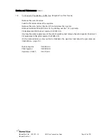
Page 27: ...cover and disconnect the plug in connections Replace in reverse order 7 To Remove Pressure Switch Working from the rear of the appliance remove the electric s cover secured by four screws Remove the pressure switch cover secured by a single screw Disconnect the four wires from the terminal block Disconnect the compression union from the sensing pipe and remove the pressure switch Replace in revers...

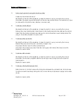
Page 28: ... the control knobs and the control panel which is secured by two fixing screws Working at the rear of the control panel disconnect the wires to the switch taking careful note of their positions Push the switch through the control panel and at the same time squeeze down onto the two tabs above and below the switch Replace in reverse order 12 To Convert NG appliances to LP Gas Single Two Tier Ovens ...

Page 29: ...ion 2 and unscrew the injector Remove Aeration Plate 927438 01 by drilling out the 1 8 pop rivets Fit Replacement NG burner injector 924905 03 Unscrew the pilot supply pipe at the pilot assembly and remove the pilot injector Section 2 Fit replacement NG pilot injector 922088 09 On the solenoid valve screw out anti clockwise the governor and adjust the gas pressure Installation page 15 Burner Injec...

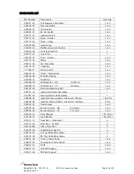
Page 30: ... 01 Pilot Body 1 or 2 922088 09 Pilot Injector NG 0 75mm 1 or 2 922088 10 Pilot Injector LP 0 26mm 1 or 2 926183 02 Electrode Retaining Nut 1 or 2 926721 G1 Ignition Electrode Assembly 1 930023 S2 Sensing Electrode Assembly 1 928006 G1 Ignition Sensing Lead c w Resistor 750mm 1 2 Tier 928006 G2 Ignition Sensing Lead c w Resistor 1000mm 2 Tier 924905 01 Oven Burner 1 or 2 924905 03 Burner Injector ...

Page 31: ... Swivel Braked 2 932811 02 Castor Swivel Unbraked 2 922088 G1 Pilot Assy NG 1 or 2 922088 G2 Pilot Assy LP 1 or 2 931897 S1 Conversion Kit NG to LPG 1 or 2 931897 S2 Conversion Kit LPG to NG 1 or 2 Spare parts available from Enodis UK Food Service Group Enodis House 5E Langley Business Centre Station Road Langley Berkshire SL3 8DS Tel 44 0 1753 485906 Fax 44 0 845 301 1463 ...

Page 32: ... Company will not be obliged to repair or replace any goods if after examination the defect damage is found to be through accident misuse neglect incorrect installation or maintenance by other than approved engineers or any other cause beyond the reasonable control of the manufacturer EXCLUSIONS TO WARRANTY Normal routine maintenance is not covered and the warranty specifically excludes any proble...

Reviews: