8
octaves. Turn the RATE knob slowly to hear the LFO's full speed range.
•Turn the RATE knob counterclockwise.
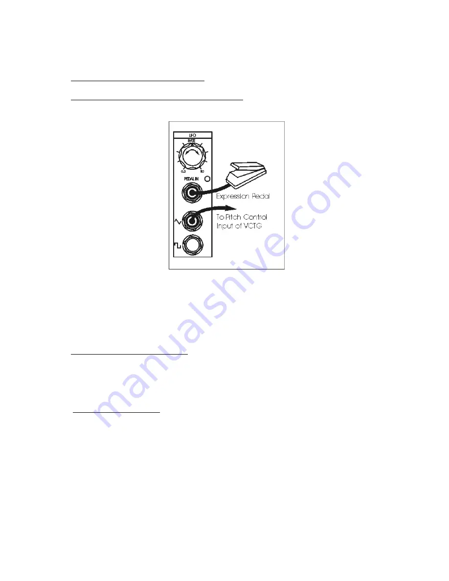
•Plug an expression pedal into the PEDAL IN jack.
Vary the setting of the pedal to hear its effect on the LFO speed.
Figure 4 - Setup for trying out the LFO module.
ATTENUATORS
An ATTENUATOR cuts down the strength of a signal. Your CP251 has two identical
attenuators, each of which has an input jack, an output jack, and a knob. When the
knob is fully clockwise, the full input signal is available at the output.
•Connect patch cords as follows:
a) From the triangular output of the LFO to the input of one ATTENUATOR,
b) From the ATTENUATOR output to the VCTG pitch control input.
• Set the knobs as follows:
a) LFO RATE to mid position, and
b) ATTENUATOR full clockwise.
You should hear the pitch vary over several octaves. Now turn the ATTENUATOR knob
counterclockwise. Note that the width of the pitch variation decreases. When the
ATTENUATOR knob is fully counterclockwise, you will not hear any pitch variation from the
LFO signal.
Next, remove the first patch cord from the LFO's triangular output, and plug it into the


