14
the LFO rate, so turning the LFO RATE knob affects how smooth the OUT 2 waveform is.
When no patch cord is plugged into the IN jack, the NOISE waveform is bridged to this
jack. When no patch cord is plugged into the TRIG jack, the LFO square waveform is
bridged to this jack.
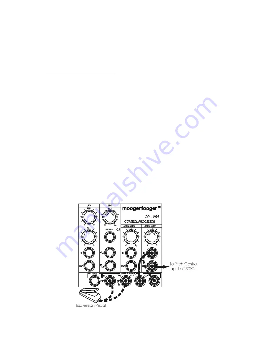
• Connect patch cords as follows:
a) from OUT 1 to an ATTENUATOR IN jack,
b) from the ATTENUATOR OUT jack to your VCTG pitch control input.
Note that the pitch is changing in random steps at the LFO rate. Vary the setting of the
LFO RATE and ATTENUATOR knobs to vary the speed and amplitude of the control
waveform.
Plug your expression pedal into the IN jack. Move the pedal back and forth. Note that
the setting of the expression pedal, rather than the NOISE waveform, is now being
sampled and held at the LFO rate.
Remove your expression pedal from the IN jack and plug it into the TRIG jack. Move
the pedal back and forth. Note that the NOISE waveform is now being sampled each
time you push the pedal back, rather than at the LFO rate.
Remove the expression pedal from the TRIG jack. Remove the patch cord from the
OUT 1 jack and then insert it into the OUT 2 jack. Note that the resulting signal is a
smoothed version of OUT 1. The rate at which the waveform changes can be varied,
from extremely slow to extremely fast, by changing the setting of the LFO RATE knob.
Figure 10 - Setup for trying out the Sample And Hold Module.


