12
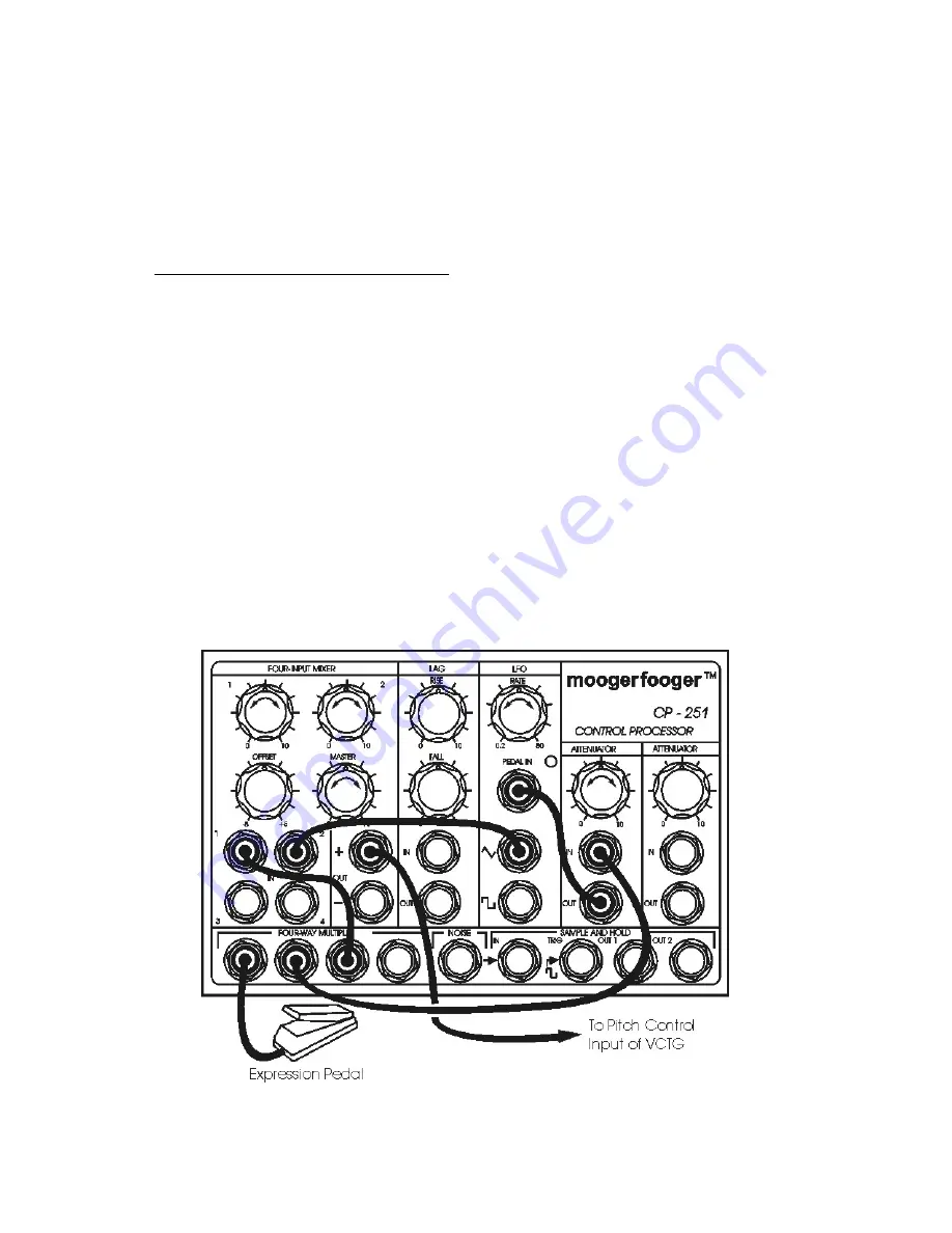
a) from one of the unused MULTIPLE jacks, to the IN jack of an ATTENUATOR,
b) from the ATTENUATOR OUT jack, to the PEDAL IN jack of the LFO.
These connections enable the expression pedal to control the LFO rate. The rate
range is determined by the setting of the attenuator knob.
• Connect more patch cords as follows:
a) from an unused MULTIPLE jack to INPUT 1 of the MIXER,
b) from the LFO TRIANGULAR output to INPUT 2 of the MIXER,
c) from the MIXER "+" output to your VCTG pitch control input.
Set all the MIXER knobs to mid-position. These connections combine the pedal
voltage with the LFO triangular waveform.
Now step on the expression pedal. Note that the tone rises in pitch and the triangular
modulation speeds up as you depress the pedal. This is because you've used the
MULTIPLE to route the pedal voltage both to the MIXER (where it is combined with the
LFO triangular wave prior to being routed to your VCTG) and through an ATTENUATOR to
the LFO pedal input, where it varies the speed of the triangular wave. Vary the setting of
each of the knobs in the MIXER, the ATTENUATOR, and the LFO to see what effect it has
on the pitch of your VCTG.
Figure 8 - Setup for trying out the Four Way Multiple.


