30
MSD Multi-Axis System Operation Manual DC-AC Servo Drive
4.3.1
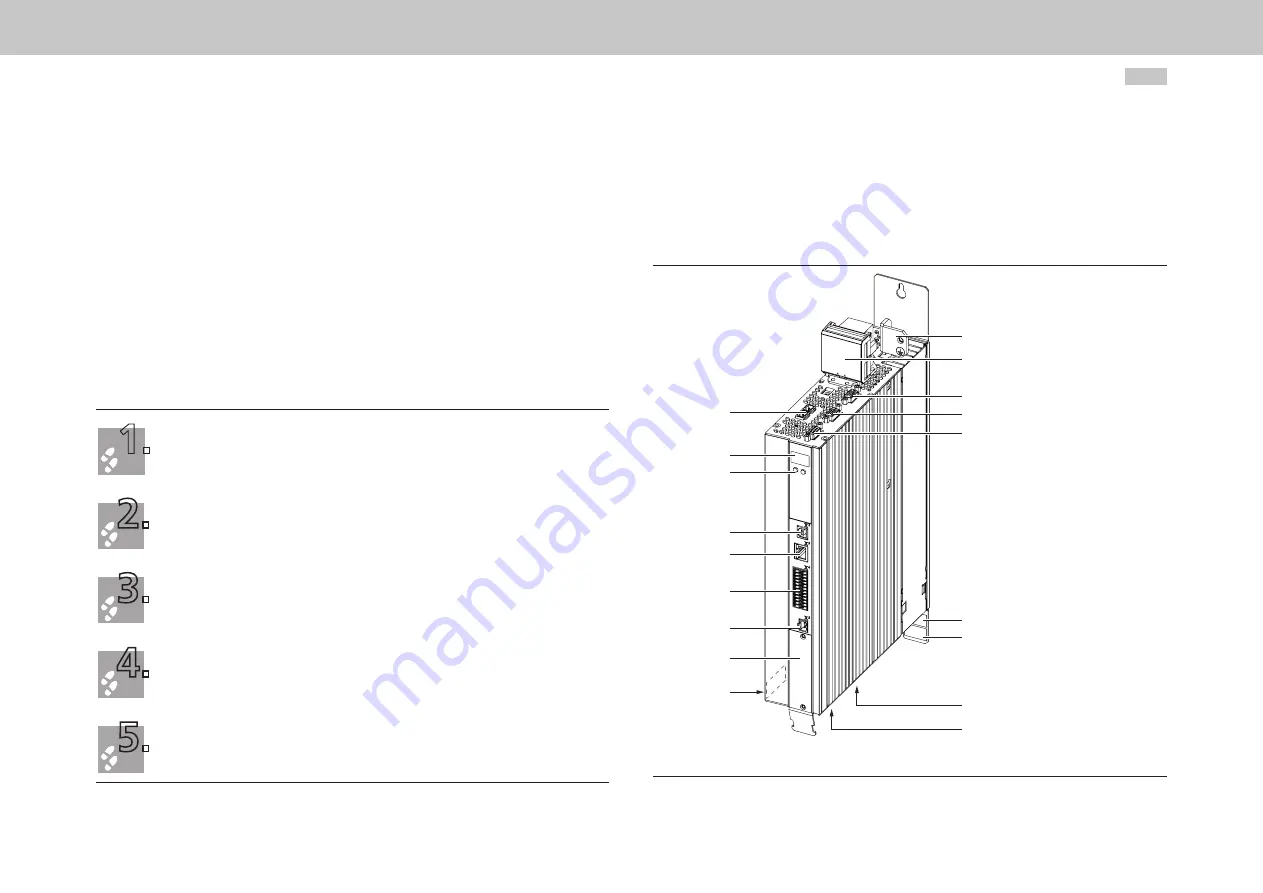
Layout, G393-004 (Size 1) to G393-032/G397-035
(Size 4)
In the following you will find the layout with the corresponding positions of the
connectors and terminals. For improved clarity we have added an abbreviation to the
designation for the connectors and terminals.
PE
X11
X8
X7
X6
SW (Size 3 + 4)
HW
X12
X13
X9, X10
X5
(Size 1+2) SW
Option 1
X4
X3
X2
T1, T2
D1, D2
HW: Hardware rating plate
SW: Software rating plate
Figure 4.4 Layout, G393-004 (Size 1) to G393-032/G397-035 (Size 4)
(based on G393-004 Size 1 as an example)
4.2.5
External components
•
Place larger loads near the supply.
•
Contactors, relays, solenoid valves (switched inductances) must be wired with
suppressors. The wiring must be directly connected to the respective coil.
•
Any switched inductance should be at least 200 mm (7.87 in) away fr
om the
process controlled assemblies.
If you require further detailed information on installation, please contact the Moog
Helpline.
4.3 Overview of the connections
1.
Determine the terminal assignment that applies to your device.
For G393-004 (Size 1) to G393-032/G397-035 (Size 4) in chapter 4.3.1, page 30
For G393-045/G397-053 (Size 5) to G393-170/G397-210 (Size 6A) in chapter 4.3.2, page 32
For G397-250 to G397-450 (Size 7) in chapter 4.3.3, page 34
2.
Connect all necessary input and output units to the control connections (chapter 4.6, page 38),
the optional interfaces (chapter 4.11, page 45) and/or (chapter 4.12, page 45) and the DC link
if necessary.
3.
Connect encoder (chapter 4.13, page 46) and motor (chapter 4.14, page 49).
4.
With the aid of the pre-assembled connection cables (DC-L), connect the protective earth conductor
(chapter 4.4, page 36) and the supply voltages (chapter 4.7, page 40).
5.
Continue with commissioning in chapter 5, page 53.
moog
Id. no.: CA97554-001 0
5
/2017
4 Electrical installation


