MSD Multi-Axis System Operation Manual DC-AC Servo Drive
49
4 Electrical installation
4.14.1 Motor connection for synchronous motors
NOTE:
To connect the servomotors in the product range please use a ready made
motor cable from Moog.
G393-004 (Size 1) to G393-032/G397-035 (Size 4)
NOTE
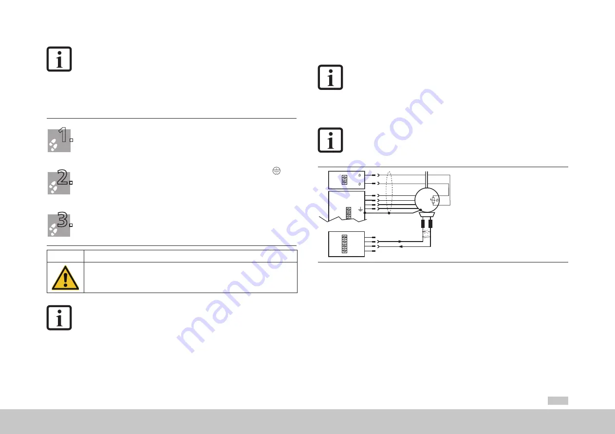
Recommended connection option for a motor brake with a motor brake
curr
ent of maximum 2 A see Figur
e 4.19.
Motor
3
U
V
W
+
-
~
X
12
X
5
Triggering of motor brake
(maximum 2 A)
GND
1
4
3
2
X
13
Figure 4.19 Connection of the motor for Size 1 to Size 4 (motor brake to 2 A)
NOTE:
The encoder supply on X7/3 is short circuit proof on
both 5 V and 11 V
operation. The controller remains in operation enabling the generation of a
corresponding error message on evaluating the encoder signals.
4.14 Motor connection
1.
Define the cable cross-section according to local and national regulations and conditions. It is
dependent on the rated current, the type of cable laying and the ambient temperature.
2.
Connect the shielded motor cable to terminals X12/ U, V, W and connect the motor to earth at
.
Connect the shield at both ends to prevent interference emissions.
Fasten shield connection plate for the motor connection X12 using both screws.
3.
Wire the temperature sensor, if fitted, to terminal X5 using separate shielded cables and activate the
temperature evaluation using Moog
D
rive
A
DministrAtor
5.
Connect the shield at both ends to prevent interference emissions.
CAUTION
!
Damage to the device due to incorrect insulation of the motor winding!
•
Carelessness can cause damage to the motor/device
The motor temperature sensor must, in relation to the motor winding, on connection to X5 be
provided with basic insulation as per IEC/EN 61800-5-1.
NOTE:
In the event of a short circuit or earth fault in the motor cable, the power stage
is disabled and an error message is issued.
moog
Id. no.: CA97554-001 0
5
/2017


