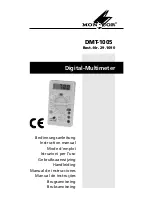
Please unfold page 3. Then you can
always see the operating elements and
connections described.
Contents
1
Operating Elements and
Connections . . . . . . . . . . . . . . . . . . . 12
2
Safety Notes . . . . . . . . . . . . . . . . . . . 13
3
Applications . . . . . . . . . . . . . . . . . . . . 13
4
Setting into Operation . . . . . . . . . . . . 14
5
Carrying out Measurements . . . . . . . 14
5.1 Voltage measurements . . . . . . . . . . . 14
5.2 Direct current measurements . . . . . . 15
5.3 Resistance measurements . . . . . . . . 16
5.4 Current amplification with transistors 16
5.5 Forward voltages with diodes . . . . . . 17
6
Replacement of Battery or Fuse . . . . 17
7
Specifications . . . . . . . . . . . . . . . . . . 18
1
Operating Elements and
Connections
1 Display
2 Range switch
3 Plug-in connections to measure the cur-
rent amplification with transistors
4 Jack “10A DC” for the red test lead (posi-
tive pole) to measure in the 10 A DC range
5 Jack “V
Ω
mA” for the red test lead (posi-
tive pole) to measure in all ranges except
in the 10 A DC range
6 Jack “COM” for the black test lead (nega-
tive pole)
GB
12


