background image

• 

• 

• 

Certifications


MiR100™ User Guide, Robot Interface 2.0, 08/2018 v.1.1

10

Reference of the other technical standards and specifications used:

See also signed copy of Declaration of conformity in Appendix D on page 42.

Ref. no.

Title

EN 1525:1997-09

Safety of industrial trucks – Driverless trucks and their systems

Summary of Contents for MiR 100

Page 1: ...User Guide October 2017 v 1 02017 v 1 2 with MiR Robot Interface 2 0 08 2018 v1 1 en...

Page 2: ...subject to change without prior notice Every precaution has been taken in the preparation of this manual Nevertheless MiR assumes no responsibility for errors or omissions or any damages resulting fro...

Page 3: ...rted 11 4 1 In the box 11 4 2 Unpacking the MiR100 12 4 2 1 Unboxing 12 4 2 2 Powering up 13 4 3 Getting connected 16 4 4 Charging the robot 17 4 5 Testing the robot 18 4 6 Shutting down the robot 19...

Page 4: ...ks 30 8 1 2 Regular checks and replacements 31 9 Repacking for transport 32 9 1 Preparations 32 9 2 Packing the robot for transportation 33 A Payload specifications 34 B Connectors pinout 38 C Certifi...

Page 5: ...ation Manuals are available on the product pages of the MiR website where you will also find video tutorials product pictures and technical specifications For example Quick starts a short getting star...

Page 6: ...words to indicate degree of danger 2 2 Safety concept Indicates an immanently hazardous situation that will result in death or severe personal injury if proper precautions are not taken Indicates a p...

Page 7: ...ations See on page 30 Avoid leakage of fluid during transport Danger of personal injury from leaking fluid Make sure that loads containing fluids do not leak during transport Use only the original cha...

Page 8: ...rface Risk of personal injury and or damage to the robot Wet and uneven surfaces may cause the robot to skid Do not overload the robot Risk of personal injury and or damage to the robot The maximum pa...

Page 9: ...robot to excessively humid or dry environment Risk of damage to the robot or robot components The ambient humidity in the robot s environment must be within the specifications see Technical specifica...

Page 10: ...immediately When the person or object is out of the safety zone again the robot will automatically reset the emergency stop MiR100 is designed with total redundant electrical safety circuit including...

Page 11: ...ted below The European directives are available on the official website https eur lex europa eu Reference to the harmonized standards used as referred to in Article 7 2 Ref no Title 2006 42 EC Directi...

Page 12: ...08 2018 v 1 1 10 Reference of the other technical standards and specifications used See also signed copy of Declaration of conformity in Appendix D on page 42 Ref no Title EN 1525 1997 09 Safety of i...

Page 13: ...rnal antenna and 4 pcs M10x40 bolts Two charging cables one for 110 V and one for 220 V 3 MiR folder containing Printed documents MiR100 Quick start in English and local language if applicable Passwor...

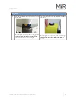
Page 14: ...xing Follow these steps to unbox the MiR100 Step Action 1 Remove pallet lid and take out the box with the MiR100 kit 2 Remove the top foam foam blocks on the sides and the pallet frames 3 Place the pa...

Page 15: ...t one of the two battery cables to the plug on top of the battery box The second cable is for an extra battery Switch on the four relays placed in the corner by the front laser scanner Start with 32A...

Page 16: ...r If a top module is going to be mounted on top of the robot the emergency stop must be placed in a position where it is easy to reach See Placing the top module on page 22 5 Connect the antenna to th...

Page 17: ...e robot The robot lights up with a yellow running light for a short moment then enters emergency stop mode indicated by a constant red light Press the reset button on the emergency stop when it has li...

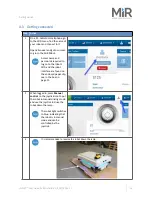
Page 18: ...name and passwords required to log on to the robot s WiFi and the robot interface are found on the enclosed paper slip see In the box on page 11 2 When logged in press Manual control on the joystick i...

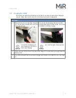
Page 19: ...ou You may have to apply a bit of force the first couple of times To avoid fast discharging it is recommended to turn off the robot while charging Then connect the charging cable to the robot s chargi...

Page 20: ...nected on page 16 2 Go to Monitoring Hardware health 3 When all components in a group are OK it is marked with a green dot If one or more components in a group are not in perfect condition the group w...

Page 21: ...repair the battery disconnect switch must be turned off as well and the battery cable disconnected see Packing the robot for transportation on page 31 Step Action 1 Bring the robot to a halt Then pus...

Page 22: ...al map contains defined locations office product delivery production hall etc that are used for logistical planning With a MiRCharge charging station the robot handles moving to a charging station aut...

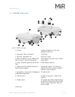
Page 23: ...n of top modules 5 Scanner reset button yellow and on off button blue 15 RJ45 Ethernet connection 6 Ultrasonic sensors for detection of transparent objects feature in progress 16 Application interface...

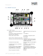
Page 24: ...elay short circuits motor for faster braking 14 MiR board interface board for gyroscope accelerometer ultrasound light on off circuit and CAN bus communication 6 Battery connector for extra battery 15...

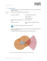
Page 25: ...two laser scanners located diagonally in the front and rear corners provide 360 protection up to 1 meter around the robot The range of the safety zones is dynamic and changes with the speed of the ro...

Page 26: ...nlight Internal sensors Internal sensors see also MiR100 Inner parts on page 22 Both gyroscope and accelerometer are placed on the MiR board Zone name Speed minimum Speed maximum Zone size Front Field...

Page 27: ...torsmartphone giveseasyaccesstooperation and monitoring of the robot Alert for lost If the robot enters a situation where it is unable to find a safe path to its destination it stops turns on the yell...

Page 28: ...eral rules for how to mount a top module 6 2 Placing the top module Top modules must be fastened using the self tightening conically shaped mooring holes in each corner of the robot and tightening tor...

Page 29: ...oad 62 5 kg Load surface 600 x 800 mm Color Pure white RAL 9010 Payload Robot payload 100 kg maximum 5 incline Towing capacity 300 kg Speed and performance Running time 10 hours or 20km Maximum speed...

Page 30: ...60 Hz Output 24 V max 15 A Environment Ambient temperature range 5 C to 50 C humidity 10 95 non condensing IP class IP 20 Communication WiFi Dual band wireless AC G N B Bluetooth 4 0 LE range 10 20 m...

Page 31: ...cations MiR100 User Guide Robot Interface 2 0 08 2018 v 1 1 29 7 2 Dimension drawing Figure 1 Dimensions of the MiR100 Top module Max height from floor to top 1800 mm Center of gravity Lower than 900...

Page 32: ...mpressed air Laser scanners Clean the optics covers of the scanners for optimum performance Avoid aggressive or abrasive cleaning agents Static charges cause dust particles to be attracted to the opti...

Page 33: ...evenly on top of the robot with connections accessible Check monthly and replace as needed Caster wheels the four corner wheels Check bearings and tighten Check weekly and replace as needed Drive whee...

Page 34: ...sport regulations see Caution below If the robot is to be sent back for service and repair the battery connector must be disconnected from the battery Lithium batteries are subject to special transpor...

Page 35: ...to a halt and push the blue power button to turn off the robot 2 Turn off the battery disconnect switch the two yellow indicators pointing to Off To pack the robot reverse the steps of the unpacking p...

Page 36: ...lustrate the center of mass CoM specifications for safe operation at different payloads The specifications apply to payloads of 25 kg 50 kg 75 kg 100 kg 200 400 800 600 1000 1200 1400 200 0 400 600 20...

Page 37: ...00 User Guide Robot Interface 2 0 08 2018 v 1 1 35 200 400 800 600 1000 1200 1400 200 0 400 600 200 400 800 600 1000 1200 1400 200 0 400 600 Units mm 50kg payload 800 600 400 200 1000 800 600 400 200...

Page 38: ...00 User Guide Robot Interface 2 0 08 2018 v 1 1 36 200 400 800 600 1000 1200 1400 200 0 400 600 200 400 800 600 1000 1200 1400 200 0 400 600 Units mm 75kg payload 800 600 400 200 1000 800 600 400 200...

Page 39: ...00 User Guide Robot Interface 2 0 08 2018 v 1 1 37 200 400 800 600 1000 1200 1400 200 0 400 600 200 400 800 600 1000 1200 1400 200 0 400 600 Units mm 100kg payload 800 600 400 200 1000 800 600 400 200...

Page 40: ...ectors pinout B 1 Application interface Figure 1 Application interface Pin number Signal name Max current Remarks 1 Battery voltage 3A Starts with the robot 2 Battery voltage 3A Starts with the robot...

Page 41: ...Remarks 1 DIN 19 2 DIN 14 3 DIN 70 4 E stop 1 GN 5 E stop 2 GN WH RD 6 Reset button BWN WH 7 SICK XTIO Q3 For Sick Scanner 8 I5 For Sick scanner 9 GND To use with the 24V signal from pin 10 10 24V max...

Page 42: ...MiR100 User Guide Robot Interface 2 0 08 2018 v 1 1 40 C Certificates C 1 Particle emission Cleanroom...

Page 43: ...MiR100 User Guide Robot Interface 2 0 08 2018 v 1 1 41...

Page 44: ...MiR100 User Guide Robot interface 2 0 08 2018 v 1 1 42 D Declaration of conformity...

Reviews: