MKS 651D Series User Manual Download Page 144


Appendix A:  Product Specifications 


132 

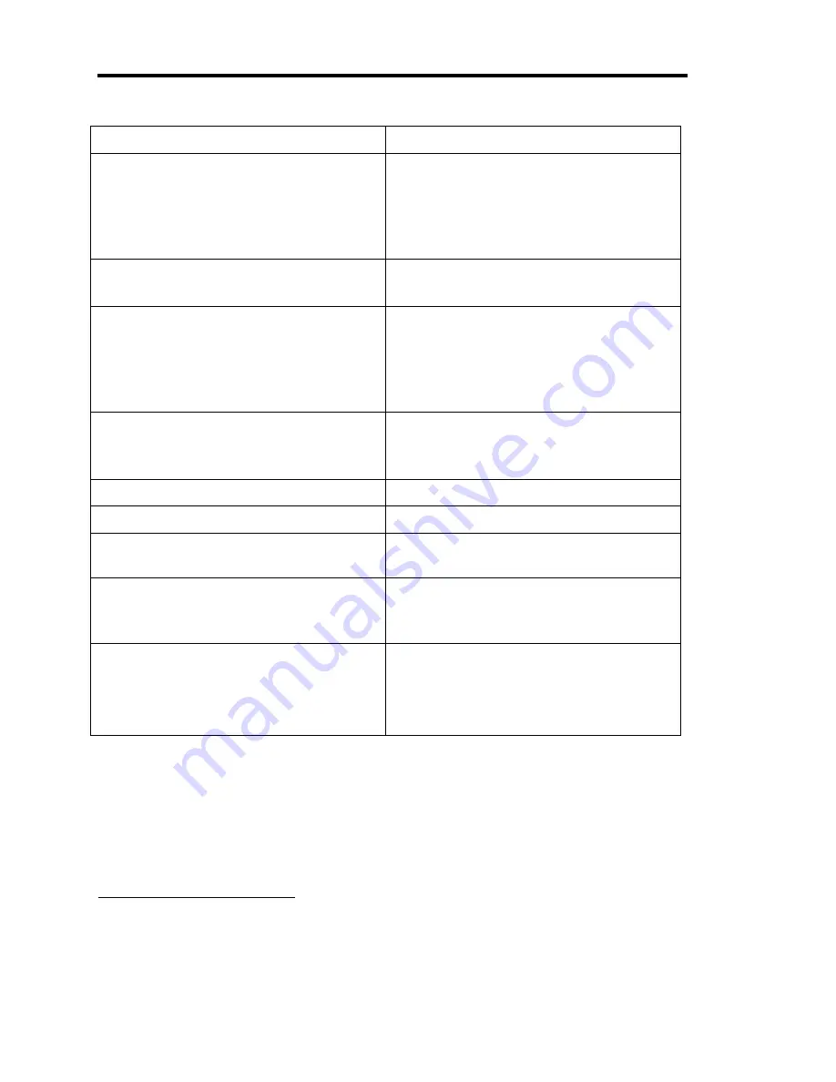
External Set Point Signal 

5 Volts or 10 Volts

*

, selectable 

Fuses 

Low power unit:    90 to 132 VAC 

 180 to 264 VAC 

High power unit:   90 to 132 VAC 

 180 to 264 VAC 


0.63A (T), 250V, 5 x 20 mm 
0.315A (T), 250V, 5 x 20 mm 

1.25A (T), 250V, 5 x 20 mm 
0.63A (T), 250V, 5 x 20 mm 

Maximum relative humidity 

80% for temperatures up to 31

°

 C, 

decreasing linearly to 50% at 40

°

 C 

Input Power 

Low power unit 
 

High power unit 


90 to 132 or 180 to 264 VAC @50/60 Hz 
75 VA (max) 

90 to 132 or 180 to 264 VAC @48/62 Hz 
150 VA (max) 

Output Power 

Low power unit 
High power unit 


±15 VDC @ 0.5 Amps (max)

4


±15 VDC @ 1.5 Amps (max) 

Overrange Pressure 

±10.5 Volts 

Pressure Input Signal 

0 to +10 Volts DC 

Pressure Units 

Torr, mTorr, mBar, µBar, Pascal, kPa, 
cmH

2

0, inH

2

Set Points 

Internal 
External 


5, each one pressure or position selectable 
1, pressure or position selectable 

Weight 

Low power unit 
High power unit 

Optional valve failsafe battery backup 


7 lbs. 3 oz. (3.26 kg) 
6 lbs. (2.04 kg) 

3 lbs. 8 oz. (1.25 kg) 

Due to continuing research and development activities, these product specifications are subject to change without notice. 


4

Derated to 0.4 Amps with 90 to 99 or 180 to 198 VAC input. 

Summary of Contents for 651D Series

Page 1: ...118965 P1 Preliminary 5 02 MKS Type 651D Pressure Controller...

Page 2: ...orm or by any means electronic or mechanical including photocopying and recording or by any information storage or retrieval system except as may be expressly permitted in writing by MKS Instruments I...

Page 3: ...Chapter Two Installation 9 How To Unpack the Type 651 Unit 9 Unpacking Checklist 9 Product Location and Requirements 10 Operating Environmental Requirements 10 Safety Conditions 10 Product Compatibil...

Page 4: ...ock Switch 30 Arrow Keys 31 Adjust Knob 31 Learn Key 31 Valve Position Control Keys 31 Set Point Selection Keys 31 Rear Panel Components 32 Valve Connector Slot 4 32 Transducer Connectors Slot 3 32 In...

Page 5: ...te a Set Point 59 How To Control the Valve 60 How To Use the Sensor Zero 61 To change the displayed sensor 61 How To Use the Special Zero 61 How To Remove the Zero Correction Factors 63 How To Zero th...

Page 6: ...ation Factor 93 How To Set the Softstart Rates 94 How To Set the Process Limit Relays 96 Control Messages 97 How To Activate a Set Point 99 How To Control the Valve 100 How To Use the Sensor Zero 101...

Page 7: ...rmation 119 Maintenance 119 How to Replace the Fuses 119 How To Replace the Memory RAM Module 121 How To Replace the Optional Valve Failsafe Battery 124 Troubleshooting 126 How To Identify an Out of R...

Page 8: ......

Page 9: ...hase Set Too Low 27 Figure 8 Front Panel of the 651 Controller 30 Figure 9 Rear Panel of the 651 Controller 32 Figure 10 Voltage and Fuse Labels 37 Figure 11 Serial Number Label 37 Figure 12 Initial D...

Page 10: ......

Page 11: ...Interface Connector Pinout 22 Table 9 Transducer Connector Pinout 23 Table 10 Valve Connector Pinout 24 Table 11 Expected Battery Life 35 Table 12 Capacity Loss of Stored Battery 36 Table 13 Full Sca...

Page 12: ......

Page 13: ...e condition or the like which if not correctly performed or adhered to could result in injury to personnel Caution The CAUTION sign denotes a hazard It calls attention to an operating procedure practi...

Page 14: ...d IEC 417 No 5019 Frame or chassis IEC 417 No 5020 Equipotentiality IEC 417 No 5021 Direct current IEC 417 No 5031 Alternating current IEC 417 No 5032 Both direct and alternating current IEC 417 No 50...

Page 15: ...el only GROUNDING THE PRODUCT This product is grounded through the grounding conductor of the power cord To avoid electrical shock plug the power cord into a properly wired receptacle before connectin...

Page 16: ...ductors or between either of the supply conductors and ground than that specified in the manual USE THE PROPER FUSE Use only a fuse of the correct type voltage rating and current rating as specified f...

Page 17: ...etup for pressure or position control one external analog set point an adjustable softstart function to minimize turbulence in the chamber and contamination of the process two process limit relays eac...

Page 18: ...ity Chapter Four Local Operation describes how to operate the controller using the front panel controls Chapter Five Remote RS 232 Operation describes the protocol and messages used to operate the uni...

Page 19: ...the use of your Type 651 controller or to obtain information about companion products MKS offers contact any authorized MKS Calibration and Service Center If it is necessary to return the controller...

Page 20: ...Customer Support Chapter One General Information 8 This page intentionally left blank...

Page 21: ...d MKS immediately If it is necessary to return the unit to MKS obtain an ERA Number Equipment Return Authorization Number from the MKS Service Center before shipping Please refer to the inside of the...

Page 22: ...ter Cables Table 4 Product Location and Requirements The Type 651 unit meets the following criteria POLLUTION DEGREE 2 in accordance with IEC 664 Transient overvoltages according to INSTALLATION CATEG...

Page 23: ...available to a transducer from a 651 controller Transducer Current Available Valve Configuration 651 Supply Type Line Voltage Range Transducer Current Available 253 653 Low power 90 to 99 VAC 50 60 H...

Page 24: ...ly grounded at both ends are required to meet CE specifications 2 To order metal braided shielded cables add an S after the cable type designation For example to order a standard cable to connect the...

Page 25: ...1 252 PLO 252 PLO VPO 651 I O CB651 14 1 CB651S 14 1 252 MSO PLO 252 MSO VPO 252 MSO VPO PLO 651 I O CB651 15 1 CB651S 15 1 152 PC VPO 152 PC VPO RS 232 651 I O CB651 16 1 CB651S 16 1 152 RZ VPO RZ VP...

Page 26: ...suffice 4 For shielded cables with flying leads at one or both ends it is important at each such end to ground the shield before the wires exit Make this ground with absolute minimum length Refer to F...

Page 27: ...ional Plastic or Metal Cable Clamp For Physical Strain Relief Figure 1 Preferred Method To Connect an Overall Metal Braided Shielded Cable Example 2 Alternate Method To Connect Cable shown on a transd...

Page 28: ...ed where the name plate value is the expected current carrying rating and not UL or CSA rated where the name plate value is nearly the current blowing rating Use of UL or CSA rated fuses will cause un...

Page 29: ...correct fuses for the line voltage selected To change the line voltage 1 Be sure that the power cord and all interface cables are disconnected from the 651 controller 2 Use a blunt instrument such as...

Page 30: ...er Two Installation 18 Warning Be sure that your 651 unit is plugged into the correct AC outlet for the selected line voltage Plugging a unit with 115V line voltage into a 230 V outlet will damage the...

Page 31: ...rial Interface Connector 2 Interface I O Connector 3 Transducer Connectors 4 Valve Connector Table 6 Rear Panel Connector Slot Labels Note The pinouts for the connectors are listed in Tables 7 to 10 p...

Page 32: ...B651S 10 10 to make the connection from the 651 unit s 9 pin serial port to a computer s 9 pin serial port Unlisted pins on this connector are not compatible with the current 9 pin Type D industry sta...

Page 33: ...Open valve low 9 Analog input channel select hi Channel 1 low Channel 2 28 output PLO 2 status low out of limit 10 Analog set point 10 29 output PLO 1 status low out of limit 11 Analog set point cont...

Page 34: ...Connectors Chapter Two Installation 22 transducer connect the negative analog set point pin 34 to analog ground pin 35 Table 8 Interface Connector Pinout...

Page 35: ...15 pin Hi Density D is for the Low Range pressure sensor Both pressure sensor connectors use the same pinout shown below Transducer Connector Pinout Pin Number Assignment 1 15 V Supply 2 Pressure inp...

Page 36: ...or Pinout Pin Number Assignment 1 Motor winding A low 2 Motor winding A high 3 Limit switch ground 4 Open limit switch signal 5 Closed limit switch signal 6 Motor winding B high 7 Motor winding B low...

Page 37: ...int uses its own gain and phase value to optimize the response from set point to set point Although there are default values for the gains you should adjust the values for optimum control Gain and Pha...

Page 38: ...oller to track the set point with zero steady state error If the phase is too low the pressure will overshoot the set point before settling in refer to Figure 5 If the phase is too high the pressure w...

Page 39: ...quickly the pressure responds to a change in set point A large gain generally results in a faster response to set point However if the gain is too small the system will be slow in responding to set po...

Page 40: ...analog set point can be configured for 5 Volt or 10 Volt full scale input The analog set point value is expressed as a percentage of full scale using the following formula ANALOG SET POINT ANALOG SET...

Page 41: ...ch are for relay 2 Use the appropriate pins to configure the relays for normally open or normally closed operation While the pressure remains within PLO limits the 651 pressure controller actuates the...

Page 42: ...lve during operation It also displays the various software menus Key Lock Switch The Key Lock switch is used to select either Local front panel or Remote rear panel control Note The switch must be set...

Page 43: ...ust Knob The adjust knob which turns clockwise and counterclockwise is used to select a parameter value Learn Key This key currently has no function Zero Key This key is used to zero an attached senso...

Page 44: ...lot 3 The 15 pin female Type D connectors are used to attach transducers to the 651 controller Refer to Table 9 on page 22 for the Transducer connector pinout Interface Connector Slot 2 The 37 pin fem...

Page 45: ...er This housing holds the unit s two fuses The fuse values are listed in Table 5 page 16 Refer to How to Replace the Fuses page 127 for more information Caution Disconnect the power cord from the 651...

Page 46: ...level above 15 5 V indicates an open fuse a disconnected battery or a defective charger The battery is continually recharged while the 651 unit is powered and operating Therefore the battery is typica...

Page 47: ...measured Refer to How To Check the Battery Voltage page 42 Local operation and How To Report the Voltage Status of the Valve Battery Back Up page 112 RS 232 operation for more information Expected Ba...

Page 48: ...nnected In fact the higher the ambient temperature the faster the capacity is lost Table 12 lists the time it takes for the battery to fall to fifty percent of its full capacity at various ambient tem...

Page 49: ...on the side of the unit lists the serial number and the product model code and displays the CE mark signifying compliance with the European CE regulations Serial Model MKS Instruments Inc Made in the...

Page 50: ...Labels Chapter Three Overview 38 This page intentionally left blank...

Page 51: ...parameter Press the key to scroll to the previous configuration parameter Use the Adjust knob to select the desired setting Press any key other than or at any time to return to the default Pressure an...

Page 52: ...module Once the battery back up is recognized the actual voltage of the battery is measured If the battery back up module is not recognized the screen reverts to the initial display screen refer to Fi...

Page 53: ...ss key to continue Figure 14 Battery Voltage Low Message If the battery voltage is above 15 5 V the screen displays Battery is high Press key to continue Figure 15 Battery Voltage High Message The sys...

Page 54: ...If the battery back up module has been recognized the screen displays BATTERY 13 5V BACK UP OPEN This screen allows you to view the actual battery voltage and the current valve configuration The valve...

Page 55: ...anel is set to Local 2 Press the and the valve CLOSE keys simultaneously for about three seconds The screen displays VALVE TYPE 253 STD Select the valve type from the options of 253 STD initial 253 FA...

Page 56: ...ess the and keys simultaneously for about three seconds The screen displays CONTROL MODE PID Select the desired pressure control mode PID 2 Press the key to advance to the next screen The screen displ...

Page 57: ...lays HIGH SENSOR RANGE 100 00 Identify the full scale range for the sensor connected to your unit The acceptable sensor ranges are shown in Table 13 on the next page 6 Press the key to advance to the...

Page 58: ...view the range of a sensor in pressure units of mBar for a sensor calibrated in Torr select the equivalent mBar unit of measure For example select 13 332 for a sensor calibrated to 10 000 Torr To dis...

Page 59: ...9 Press the key to advance to the next screen The screen displays SENSOR SIGNAL 10 VOLTS Select the full scale voltage range for the pressure sensor input from the options of 1 Volt 5 Volts and 10 Vo...

Page 60: ...oints B to E Note 1 Refer to How to Adjust the Set Point Parameters for information on how to define the set point values 2 The analog set point control pressure or position is controlled by the digit...

Page 61: ...essary to use softstart control in your process leave the softstart rate at the initial setting of 100 18 Press the key to advance to the next screen The screen displays SOFT START RATE CLOSE 100 Set...

Page 62: ...screen displays the actual voltage level of the battery along with the position the valve is currently set to drive to upon a power loss Select whether the valve will be driven fully open fully closed...

Page 63: ...pressure set points you have access to the gain and phase values Refer to PID Control with Pressure Set Points to set the gain and phase values If your set points are under position control there are...

Page 64: ...ed units SP A 100 mTorr PRES 100 mTorr L Adjust the set point value to the desired pressure In this example set point A is a pressure value of 100 mTorr and the system pressure is 100 mTorr 3 Press th...

Page 65: ...the high range gain Enter the Gain Comp Factor value range from 0 to 100 of High range sensor Gain For example if Gain value 90 0 And GCF 50 Then Gain used for low range 45 0 6 Press the key to advan...

Page 66: ...plays MINIMUM DELTA P 10000 Torr This value is the required difference between the new set point and the current pressure in the system before the backfill control feature operates Set point changes l...

Page 67: ...our Local Operation Setup 55 Enter the Setpoint backfill limit value range from 10 to 100 10 Repeat steps 2 to 4 for set points B to E These menu screens only appear when Setpoint A is in Pressure con...

Page 68: ...and Position display appears on the screen 2 Press the key to advance to the first set point menu screen The screen displays SP A 60 0 Pos PRES 2 000 Torr L Adjust the set point to the desired valve...

Page 69: ...LIMIT 1 LOW 99 00 Torr Select the desired pressure value for the low trip point of process limit 1 2 Press the key to advance to the next screen The screen displays PROCESS LIMIT 1 HIGH 0 00 Torr Sele...

Page 70: ...al screen only For example if the analog set point is configured for 5 V full scale input and the actual input applied is 5 V the analog set point display shows a value of 100 However if the actual in...

Page 71: ...e When the 651 unit is configured for PID control two gain parameters are maintained for each pressure set point When an analog set point is used with PID control the gain parameters associated with a...

Page 72: ...ing the throttle valve to full open and displaying the default Pressure and Position display screen How To Drive the Valve to Full Close To drive the valve to full close 1 Press the CLOSE key The syst...

Page 73: ...ey remains on as the sensor is zeroed The front panel display shows a pressure reading of zero and changes to reflect changes in system pressure as soon as a change occurs Note If the pressure reading...

Page 74: ...ZERO BASE PRESSURE 0 0 2 Adjust the pressure reading on the display until it matches the known base pressure reading as measured by another transducer in the system 3 Press any key to return to the de...

Page 75: ...o pressure reading to the uncorrected signal level 2 Press the STOP key to return to the default Pressure and Position display screen How To Zero the Analog Set Point This function instructs the contr...

Page 76: ...using the analog set point display For example if the analog set point is configured for 5 V full scale input and the actual input applied is 5 V the analog set point display shows a value of 100 How...

Page 77: ...point is adjusted correctly turn the adjust knob until the reading flickers between 99 99 and 100 00 Note 1 The display reads 100 00 for an overrange reading as well as a true 100 reading 2 If the cu...

Page 78: ......

Page 79: ...nel menu there are no RS 232 commands for these settings Refer to How To Set the Operating Parameters for information on setting the communication parameters When the Key Lock switch on the front pane...

Page 80: ...d value where command is a label that allows you to identify the command and value identifies the task or parameter to be changed Requests R are numbered chronologically from 1 to 52 each with a diffe...

Page 81: ...desired action to the ENTER key The 651 controller appends an end of line delimiter to the end of every response Priority and Timing of Command Execution Each RS 232 command is executed in the order t...

Page 82: ...06 cm H2O 07 in H2O R 34 F value value 00 Torr 01 mTorr 02 mBar 03 Bar 04 kPa 05 Pa 06 cm H2O 07 in H2O Backfill Valve Control Enable BE0 Disabled BE1 Enabled RBE BE0 Disabled BE1 Enabled Backfill Li...

Page 83: ...alve closes at power failure Sensor Type U value value 0 Absolute R 36 U value value 0 Absolute Sensor Signal Input Range G value value 0 1 V 1 5 V 2 10 V R 35 G value value 0 1 V 1 5 V 2 10 V Sensor...

Page 84: ...08 100 22 200 09 500 10 1000 11 5000 12 10000 13 1 33 mBar 14 2 66 15 13 33 16 133 3 17 1333 18 6666 19 13332 R 33 EH value value 00 0 1 Torr 01 0 2 02 0 5 03 1 04 2 05 5 06 10 21 20 07 50 08 100 22...

Page 85: ...dentifies the type of valve you want to control where type 1 Standard 253 valve initial 2 Fast 253 valve 3 653 valve To check the type of valve selected issue the request R 23 The controller responds...

Page 86: ...es Chapter Five Remote RS 232 Operation 74 How To Read the Pressure Control Mode To query the current control mode setting issue the request R 51 The controller responds with the message V value where...

Page 87: ...To query the current pressure units enter R 34 The controller responds with the message F value where value 00 Torr initial 01 mTorr 02 mBar 03 Bar 04 kPa 05 Pa 06 cm H20 07 in H20 An example response...

Page 88: ...led default BE1 Enabled To report the status of the feature enter RBE The controller responds with the message BEvalue where BE0 Disabled BE1 Enabled How To Set the Set Point Backfill Limit This param...

Page 89: ...lue where value is a percentage of the high range pressure transducer full scale 0 to 100 How To Set the Valve Position Signal Output Range The command B value configures the full scale voltage range...

Page 90: ...alve battery back up control issue the request R 40 The controller responds with the message K value where value 0 Option disabled 1 Valve opens at power failure 2 Valve closes at power failure An exa...

Page 91: ...RS 232 Operation Setup Messages 79 How To Read the Sensor Type To query the current sensor type issue the request R 36 The controller responds with the message U value where value 0 Absolute An examp...

Page 92: ...sets the full scale voltage range for the pressure sensor input where value 0 1 Volt 1 5 Volts 2 10 Volts initial To query the current range of the sensor signal input issue the request R 35 The cont...

Page 93: ...rent pressure ranges use this command to identify the range of your sensor Sensor Range Values Value Sensor Range Value Sensor Range 00 0 1 Torr 10 1000 Torr 01 0 2 11 5000 02 0 5 12 10000 03 1 13 1 3...

Page 94: ...ensor The controller responds with the message Ex value where x corresponds to either H or L for High or Low sensor range and value corresponds to a valid sensor range shown in Table 14 page 81 An exa...

Page 95: ...e same regardless of your system s configuration The way your unit responds to the gain or phase messages depends on the type of pressure control PID and set point control pressure or position chosen...

Page 96: ...ange A value value 0 5 V 1 10 V R 24 A value value 0 5 V 1 10 V Set Point Values S x value x 1 Set Point A 2 Set Point B 3 Set Point C 4 Set Point D 5 Set Point E 6 Analog Set Pt value Set points A to...

Page 97: ...e 0 to 100 0 RGC GCvalue value 0 to 100 0 Phase Compensation Factor PCvalue value 0 to 100 0 RPC PCvalue value 0 to 100 0 Softstart Rates I x value x 1 Set Point A 2 Set Point B 3 Set Point C 4 Set Po...

Page 98: ...1 Note The RS 232 command T6 value overrides the digital logic control for the analog set point To report the type of valve control for a particular set point issue the request R xx where xx 25 Analo...

Page 99: ...R 24 The controller responds with the message A range where value 0 5 Volts 1 10 Volts An example response if the analog set point has a full scale range of 5 Volts is A 0 To change the full scale ra...

Page 100: ...o E of full scale with pressure control of open with position control analog set point 0 0 to 100 of the controlling transducer s range normal resolution initial 1 0 to 10 of the controlling transduce...

Page 101: ...point of the analog set point FS voltage range To report the value for set point A enter R 1 An example response if set point A is set to 50 of full scale pressure is S 1 50 To report the value for t...

Page 102: ...point A to 50 enter M 1 50 To report the gain value for any set point issue the request R xx where xx 46 Set point A gain 47 Set point B gain 48 Set point C gain 49 Set point D gain 50 Set point E ga...

Page 103: ...alue command When the controller receives a set point in the range of the low range sensor Channel 2 it uses a percentage of the high range gain determined by the GCF The messages described here set a...

Page 104: ...oint A to 5 enter X 1 5 To report the Phase value for any set point issue the request R xx where xx 41 Set point A Phase 42 Set point B Phase 43 Set point C Phase 44 Set point D Phase 45 Set point E P...

Page 105: ...ue command When the controller receives a set point in the range of the low sensor it uses a percentage of the high range phase determined by the PCF The messages described here set and report the pha...

Page 106: ...point C rate 4 Set point D rate 5 Set point E rate 6 Analog set point rate 7 Valve open rate 8 Valve close rate value 0 1 slowest to 100 fastest of valve full speed To report the softstart rate for an...

Page 107: ...Chapter Five Remote RS 232 Operation Setup Messages 95 To change the softstart rate for set point A to 50 enter I 1 50...

Page 108: ...2 High threshold Process Limit 1 13 Low threshold Process Limit 2 14 High threshold Process Limit 2 The controller responds with the message P x value where x 1 Low threshold Process Limit 1 2 High th...

Page 109: ...et Point D 5 Set Point E 0 Analog Set Pt R7 M x y z w X Active Set Point 0 Analog Set Pt 1 Set Point A 2 Set Point B 3 Set Point C 4 Set Point D 5 Set Point E 6 Valve Open 7 Valve Closed 8 Valve Stop...

Page 110: ...zeros base pressure Z 2 value value FS pressure None None Remove Sensor and Special Zeros removes Z1 and Z2 value Z 3 None None Zero Analog Set Point Z 4 None None Calibrate Analog Set Point Full Sca...

Page 111: ...x Active Set Point y Valve Status 0 Analog set point 0 Controlling 1 Set point A 1 Valve open 2 Set point B 2 Valve close 3 Set point C 4 Set point D z Pressure 5 Set point E 6 Valve open 0 Pressure...

Page 112: ...he front panel driving the throttle valve to full open and displaying the default Pressure and Position display screen How to Drive the Valve to Full Close To drive the valve to full close issue the c...

Page 113: ...shows a pressure reading of zero and changes to reflect changes in system pressure as soon as a change occurs To remove the sensor zero correction refer to How To Remove the Sensor and Special Zeros...

Page 114: ...s function To remove the zero corrections send the command Z 3 How To Zero the Analog Set Point The command Z 4 instructs the controller to take the current value of the external analog set point for...

Page 115: ...input applied is 2 5 V the unit reports a value of 50 To recalibrate the full scale of the analog set point 1 Apply full scale input voltage for example 4 5 V to pins 33 and 34 on the Interface conne...

Page 116: ...e reading as of FS R 5 P value value FS Valve Position Value reports valve position as of Open R6 V value Value Open System Status reports type of operation state of learning valve control R 37 M x y...

Page 117: ...l valve failsafe battery back up R 39 BT x x 0 Battery voltage is out of range 1 Battery voltage is within acceptable range 2 Battery back up option is not installed Firmware Version reports the insta...

Page 118: ...x value command Refer to How To Set the Sensor Range for more information An example response if the pressure is 10 Torr for a 10 Torr FS unit is P 100 The pressure reading is 100 of the sensor s full...

Page 119: ...the Valve Position Value To report the valve position value as a percentage of full Open issue the request R 6 The controller responds with the message V value where value of full Open Example if the...

Page 120: ...s issue the request R 37 The controller responds with the message M x y z where X Type of Operation 0 Local 1 Remote Y State of the Learn Function 0 Not learning 2 Learning valve Z Valve Control 0 Ope...

Page 121: ...x 0 Battery voltage is out of range 1 Battery voltage is within acceptable range 2 Battery back up option is not installed Note The normal voltage range of the battery ranges from 11 V to 15 5 V A vo...

Page 122: ...the A D calibration is OK is CS 0 An example response if the A D calibration is out of range is CS 1 If the controller detects a checksum error perform a full calibration to correct the problem Refer...

Page 123: ...each digital input is listed in Table 17 page 112 To select an input function pull the appropriate input pin to a TTL low level 0 to 0 8 Volts for a minimum of 50 milliseconds If a higher priority fun...

Page 124: ...unction with another valve control function 8 Low High Close the valve No function 9 Low Ch 2 Hi Ch 1 Analog Input Channel Select 10 Low High FS analog set point yields 1 10 the FS pressure of the con...

Page 125: ...the valve No function 27 Low High Open the valve No function Table 17 Digital Input Functions How To Set the Analog Set Point Inputs The analog set point inputs set point and set point pins 33 and 34...

Page 126: ...tal inputs are held low lower priority signals are blocked that is they are not recognized until the higher priority signal is released 3 25 Remote zero 4 5 No function 5 8 Close valve 6 27 Open valve...

Page 127: ...utput is listed in Table 19 page 116 The approximate time constant of the outputs are 2 5 microseconds Each output includes a 240 ohms series resistor to protect it against line surges and spikes Addi...

Page 128: ...State Digital Output Function 19 Low High Valve is not open Valve is open 23 Low High Valve is not closed Valve is closed 28 Low High Pressure outside of PLO 2 band relay is not energized Pressure ins...

Page 129: ...n applies to the use of TTL commands to Open the valve Close the valve or use a setpoint The softstart rate for the active set point is controlled by the state of digital logic input pin 7 on the Inte...

Page 130: ...How To Activate the Softstart Rate Chapter Six Remote Digital Logic Control 118 This page intentionally left blank...

Page 131: ...xic materials Maintenance Periodically check for wear on the cables and inspect the enclosure for visible signs of damage How to Replace the Fuses The fuses are IEC rated where the name plate value is...

Page 132: ...holder Refer to Figure 18 below for the location of the fuse holder clip Fuse Holder Clip Figure 18 Fuse Holder 5 Gently press against the clip and push up with the screwdriver until the plastic fuse...

Page 133: ...8Z32B 10 Dallas Semiconductor DS 1230AB 100 How To Remove the CPU Board Warning The 651 unit has lethal voltages inside Servicing of the unit must be performed by qualified personnel only To avoid an...

Page 134: ...h end of the board and rock it until it loosens from its position and lift the board up and out of the unit How To Replace the RAM Module 1 Locate the battery backed RAM module on the CPU board Refer...

Page 135: ...space for easy board removal the next time it is required 4 Slide the cover from rear to front into place at the front panel using the clips on the cover as a guide 5 Position the cover so that the c...

Page 136: ...er from the rear chassis by lifting it up from the clips 5 Remove the top cover by firmly pulling it up and back to clear the top of the connector plates 6 Locate the area of the unit where the chassi...

Page 137: ...lot Be sure to keep the cable away from the heatsink 20 Replace the two screws that attach the circuit assembly to its chassis and the screw removed from the left side of the housing 21 Position the f...

Page 138: ...Pressure Condition An out of range condition occurs at 105 of FS 10 5 Volts at sensor input and is displayed as a positive or negative polarity An example of a positive out of range pressure conditio...

Page 139: ...alibration to correct the problem To perform a full calibration 1 Calibrate the span of the A D converter Refer to How To Calibrate the Span of the A D Converter page 128 2 Zero the analog set point R...

Page 140: ...the A D converter 1 Apply a known voltage of between 6 6 Volts and 7 4 Volts to the pressure input pins 2 and 12 on the Transducer connector connect pin 12 to pin 5 Refer to Table 9 page 22 for the Tr...

Page 141: ...signs it to the converter reading of the pressure as an analog input In this example the 7 V input 70 00 Calibrating the span of the A D converter may take up to 5 seconds 3 Check that the calibration...

Page 142: ...Troubleshooting Chapter Seven Maintenance and Troubleshooting 130 This page intentionally left blank...

Page 143: ...erface Transducers Valve 9 pin Type D male 37 pin Type D female 15 pin Type D female Stand Hi Dens 9 pin Type D female Controller Repeatability 0 1 of FS Digital Interface Inputs 16 HCMOS pulled high...

Page 144: ...132 or 180 to 264 VAC 48 62 Hz 150 VA max Output Power Low power unit High power unit 15 VDC 0 5 Amps max 4 15 VDC 1 5 Amps max Overrange Pressure 10 5 Volts Pressure Input Signal 0 to 10 Volts DC Pr...

Page 145: ...l code when you order the unit The model code is identified as follows 651D X Y Z C D where Type Number Interface Valve Driver Power Supply Options C Y Z 651D Display X D Type Number 651D This designa...

Page 146: ...ated by a single letter code Ordering Code Stepper motor S Power Supply C Two power supplies are available designated by a single number code Ordering Code 0 5 Amp 1 1 5 Amp 2 Options D The battery ba...

Page 147: ...test configuration not the initial configuration Initial Settings Parameter Initial Setting Other Analog Set Point None None Analog Set Point Full Scale Range 5 V 10 V Baud Rate 9600 300 19200 1200 38...

Page 148: ...ensor Type Absolute None Set Point Control Pressure Position Soft Start Rate 100 User selectable 0 1 to 100 Valve Failsafe Battery Back Up Option None Close Open Disable Valve Signal Output Range anal...

Page 149: ...Appendix C Initial Settings 137 This page intentionally left blank...

Page 150: ......

Page 151: ...nal Output Range R 31 B value value 0 5 V 1 10 V BE value value 0 Disable 1 Enable BackFill RBE BE value value 0 Disable 1 Enable BL value BackFill Limit RBL BL value C Valve Close drives valve fully...

Page 152: ...20 07 50 08 100 22 200 09 500 10 1000 11 5000 12 10000 13 1 33 mBar 14 2 66 15 13 33 16 133 3 17 1333 18 6666 19 13332 Sensor Range High or Low R 33 High R55 Low Ex value x H or L value 00 0 1 Torr 0...

Page 153: ...nt C 4 Set Point D 5 Set Point E 6 Analog Set Pt 7 Valve open 8 Valve close value 0 1 to 100 full speed Softstart Rates R xx xx 15 Set Point A 16 Set Point B 17 Set Point C 18 Set Point D 19 Set Point...

Page 154: ...ued Command Description Request Response MD value Minimum Difference RMD MD value O Valve Open drives valve fully open None None P x value x 1 Low PL1 2 High PL1 3 Low PL2 4 High PL2 value Pressure li...

Page 155: ...log set point FS voltage range Table 20 RS 232 Message Summary Continued on next page RS 232 Message Summary Continued Command Description Request Response System Status NO COMMAND Reports type of lea...

Page 156: ...51 V value value 1 PID Valve Battery Back Up Status NO COMMAND Reports the voltage status of the optional valve failsafe battery back up R 39 BT x x 0 Battery voltage is out of range 1 Battery voltag...

Page 157: ...nt Full Scale R 0 S 0 value value of the analog set point FS voltage range Z 1 Sensor Zero corrects sensor zero offsets None None Z 2 value value FS pressure Special Zero zeros base pressure None None...

Page 158: ...Appendix E RS 232 Message Summary 146 This page intentionally left blank...

Page 159: ...label 37 B Batteries description of 5 Baud rate 44 C Cables adapter 13 Calibration analog set point 64 103 span of A D converter 128 30 valve 43 73 Checksum status 110 127 Command priority and timing...

Page 160: ...lation category 10 Integral gain 27 K Key lock switch 5 L Labels 37 Line voltage selector 17 M Maintenance 119 fuse replacement 119 20 RAM module replacement 121 23 valve battery back up replacement 1...

Page 161: ...3 Sensor full scale range local 45 RS 232 81 input signal voltage local 47 RS 232 80 special zero local 61 RS 232 101 zero local 61 RS 232 101 zero corrections removing local 63 RS 232 102 Serial num...

Page 162: ...ack up battery life 35 battery storage 36 control local 50 RS 232 77 replacement 124 25 status local 50 RS 232 109 threshold voltage 35 valve positions 34 voltage 34 Voltage and fuse label 37 Z Zero a...

Reviews: