7-31
Chapter 7 ASSEMBLY OF BASIC ENGINE
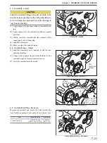
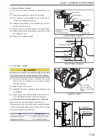
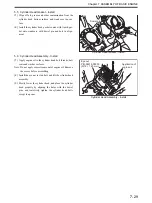
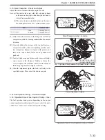
5.8 Bridges and Bridge Caps - Install
(1)
Apply engine oil to the bridge guide.
(2)
Install the bridge on bridge guide. Place the screw-fit-
ted end of bridge to exhaust manifold side.
(3)
Apply engine oil to the bridge contact area of bridge
cap, and install the bridge cap.Be careful not to drop the
bridge cap inside crankcase through push rod hole.
Bridges and Bridge Caps - Install
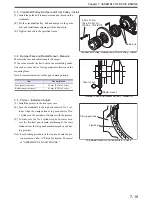
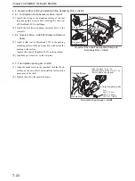
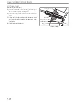
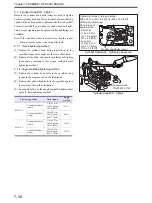
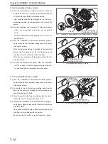
5.9 Valve Bridge and Adjusting Screw - Adjust
Adjust the contact of valve stem top faces to ensure bridge
smooth sliding on bridge guide and balanced pushing to
valves.
(1)
Loosen the adjusting screw so that its top face protrudes
from top face of nut by 6 to 7 mm [0.23 to 0.27 in.]
(2)
Press the top of bridge by hand so that the top face of
valve stem on bridge plane end contacts closely to the
bridge pushing face.
(3)
Turn the adjusting screw slowly until screw contacts
the top face of valve stem. Then, turn the screw further
by 10°, and tighten lock nut to the specified torque.
Valve Bridge and Adjusting Screw - Adjust
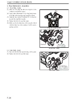
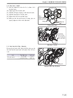
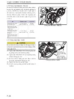
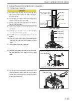
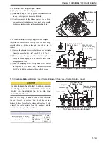
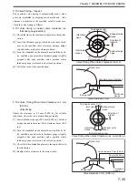
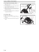
5.10 Clearance Between Bottom Face of Valve Bridge and Top Face of Valve Rotator - Inspect
Push the valve bridge by hand to make close contact of the
top end face of valve stem. Then, check the clearance
between bottom face of valve bridge and top face of valve
rotator.If the value deviates from the standard, find the
causal parts, and replace them with new ones.
Clearance Between Bottom Face of Valve Bridge and
Top Face of Valve Rotator - Inspect
Application of
engine oil
Bridge cap
Hold down the top of
bridge by hand.
55 ± 5.5 N·m
{5.6 ± 0.56 kgf·m}
[41 ± 4.1 lbf·ft]
Tighten an
additional 10
゜
Valve
bridge-valve
contact
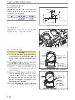
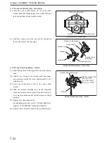
Be sure to keep the standard clearance between
valve bridge and valve rotator.If the clearance is
smaller than the standard, the valve cotter may
come off or get damage.
Item
Standard value
Clearance Between the Bottom
Face of Valve Bridge and the Top
Face of Valve Rotator
Adjusting screw
side
2.5 mm
[0.098 in.]
Non adjusting
side
1.5 mm
[0.0591 in.]
Hold down the top
of bridge by hand.
Clearance between
valve bridge bottom
face and valve
rotator top face
Valve rotator
Bridge cap
Valve bridge
Summary of Contents for S12A2
Page 1: ...SERVICE MANUAL September 2010 Pub No 99269 20170 199269 20170 ...
Page 2: ......
Page 16: ......
Page 20: ......
Page 42: ......
Page 44: ......
Page 68: ......
Page 69: ...3 1 Chapter 3 SERVICE TOOLS 1 Special Tools 3 3 ...
Page 70: ......
Page 78: ......
Page 82: ......
Page 136: ......
Page 174: ......
Page 218: ......
Page 220: ......
Page 242: ......
Page 244: ......
Page 294: ......
Page 310: ......
Page 320: ......
Page 322: ......
Page 334: ......
Page 354: ......

