background image

3-73 

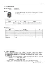
  External I/O cable


3 Controller

(4) External I/O cable

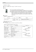
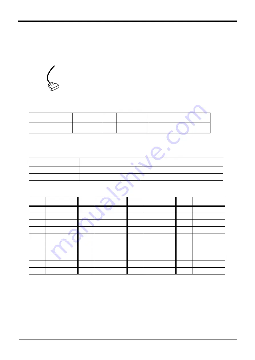
■ Order type  : ● 2D-CBL □□   Note) The numbers in the boxes □□ refer to the length. (05: 5m、 15: 15m)

■ Outline

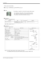
This is the dedicated cable used to connect an external peripheral device to the con

-

nector on the parallel I/O interface. For parallel I/O unit is another option 2A-CBL.**. 

One end matches the connector on the parallel input/output unit, and the other end is 

free. Connect the peripheral device's input/output signal using the free end. 

One cable correspond to the input 16 points and output 16 points. 

Two cables are needed to connection of (input 32 points and output 32 points) with 

built-in standard.

■ Configuration

Table 3-19 : Configuration device

■ Specifications

Table 3-20 : Specifications

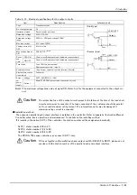
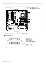
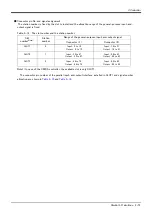
■ Connector pin numbers and cable colors

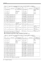
Table 3-21 : Connector pin numbers and cable colors

Notes) Pin number of connector<1> are  1C, 2C, ....20C, 1D, 2D, ....20D, connector<2> are  1A, 2A, ....20A, 1B, 

2B, ....20B.

Part name

Type

Qty.

Mass(kg)

Note1) 

Note1) Mass indicates one set.

Remarks

External I/O cable

2D-CBL □□

1 pc.

0.7(5m)

1.84(15m)

5m or 15m

Items

Specifications

Number of cables x cable size

AWG #28 x 20P (40 pairs)

Total length

5m、 15m

Pin no. 

Cable colors 

Pin no. 

Cable colors 

Pin no. 

Cable colors 

Pin no. 

Cable colors 

1A/C

Orange/Red a

11A/C

Orange/Red c

1B/D

Orange/Black a

11B/D

Orange/Black c

2A/C

Gray/Red a

12A/C

Gray/Red c

2B/D

Gray/Black a

12B/D

Gray/Black c

3A/C

White/Red a

13A/C

White/Red c

3B/D

White/Black a

13B/D

White/Black c

4A/C

Yellow/Red a

14A/C

Yellow/Red c

4B/D

Yellow/Black a

14B/D

Yellow/Black c

5A/C

Pink/Red a

15A/C

Pink/Red c

5B/D

Pink/Black a

15B/D

Pink/Black c

6A/C

Orange/Red b

16A/C

Orange/Red d

6B/D

Orange/Black b

16B/D

Orange/Black d

7A/C

Gray/Red b

17A/C

Gray/Red d

7B/D

Gray/Black b

17B/D

Gray/Black d

8A/C

White/Red b

18A/C

White/Red d

8B/D

White/Black b

18B/D

White/Black d

9A/C

Yellow/Red b

19A/C

Yellow/Red d

9B/D

Yellow/Black b

19B/D

Yellow/Black d

10A/C

Pink/Red b

20A/C

Pink/Red d

10B/D

Pink/Black b

20B/D

Pink/Black d

Summary of Contents for MELFA RV-2SD Series

Page 1: ...Mitsubishi Industrial Robot SDSeries RV 2SD 2SDB Standard Specifications Manual CR1DA 700 series Controller BFP A8790 R...

Page 2: ......

Page 3: ...on the start switch etc This also applies to maintenance work with the power source turned ON Indication of teaching work in progress Provide a fence or enclosure during operation to prevent contact...

Page 4: ...this could lead to malfunctioning by noise or to electric shock accidents Indicate the operation state during robot operation Failure to indicate the state could lead to operators approaching the rob...

Page 5: ...d Use the network equipments personal computer USB hub LAN hub etc confirmed by manufacturer The thing unsuitable for the FA environment related with conformity temperature or noise exists in the equi...

Page 6: ...on article of the USB cable was corrected The depth in which the screw of the mechanical interface section is tightened was added 2011 06 01 BFP A8790 M The user s guide was added based on South Korea...

Page 7: ...1 RV 2SD standard specification CE marking S16 specification 2 12 2 RV 2SDB S15 CE marking S15 specification 2 13 3 Operating range Common to the standard CE Marking 2 14 2 5 Tooling 2 15 2 5 1 Wirin...

Page 8: ...terface 3 67 4 External I O cable 3 73 5 Parallel I O unit 3 75 6 External I O cable 3 84 7 Personal computer cable 3 86 8 CC Link interface 3 87 9 Extension memory cassette 3 90 10 RT ToolBox2 RT Too...

Page 9: ...tions and a command list Page 95 4 Software separately About KC mark specifications This robot acquires certification of KC mark by the special specification S19 Although the three kinds of controlle...

Page 10: ...bolts 5 Earth leakage breaker CR1DA 700 series only 6 Safety manual Instruction manual CD ROM Instruction manual 7 Guarantee card 1 1 2 Special specifications For the special specifications some stan...

Page 11: ...n machine cable The type name of the CE Marking specification etc is shown in Table 1 2 Interpret the description of these type names in this volume as the CE Marking specification Table 1 2 Robot mod...

Page 12: ...cation Fix type 1S CBL 11 Flex type 1S LCBL 11 CE marking S15 specification Fix type 1S CBL 03 Flex type 1S LCBL 03 Note1 refer the length Refer to Page 5 Table 1 3 for details Note2 Extend by adding...

Page 13: ...sette 2D TZ454 Parallel I O unit 2A RZ361 Sink 2A RZ371 Source External I O cable 2D CBL05 5m 2D CBL15 15m PLC Programmable Logic Controller External device Prepared by customer Teaching pendant T B R...

Page 14: ...4x4 Simple teaching pendant R32TB Cable length 7m With 3 position deadman switch IP65 R32TB 15 Cable length 15m Highly efficient teaching pendant R56TB Cable length 7m R56TB 15 Cable length 15m Pneum...

Page 15: ...with conformity temperature or noise exists in the equipments connected to USB RS 232 or LAN When using network equipment measures against the noise such as measures against EMI and the addition of th...

Page 16: ...the value on the mechanical interface surface when all axes are combined mm sec Load MaximumNote4 Note4 The maximum load capacity is the mass with the mechanical interface posture facing down word at...

Page 17: ...is turned OFF or a stop operation is performed halfway 4 Temperature factors 1 When the operating environment temperature changes 2 When accuracy is required before and after a warm up operation 5 Fa...

Page 18: ...allowable range mentioned previously an overload or generate an overcurrnt alarm could occur In such cases it will be necessary to change the time setting for acceleration deceler ation the operating...

Page 19: ...protection standard for approach in the dangerous spot in the tool It indicates the protective structure that the proximity probe 2 5mm in diameter must not advance The IEC IP symbols define the degre...

Page 20: ...ames of each part of the robot Fig 2 2 Names of each part of the robot J1 J2 J3 J4 J5 J6 Fore arm J4 axis Twist Wrist J5 axis J6 axis Roll Roll J3 axis Upper arm J2 axis Waist J1 axis Shoulder Mechani...

Page 21: ...sions standard specification CE marking S16 specification Rz 25 Rz 25 B C View C depth 6 screw screw depth 6 depth 6 screw screw depth 6 depth 6 screw Grounding screw Minimum depth 8 depth 8 depth 6 d...

Page 22: ...5 specification View C depth 6 screw 2 M3 screw depth 6 screw screw depth 6 depth 6 screw Grounding screw Minimum depth 8 screw depth 8 depth 6 Installation Installation installation hole View A View...

Page 23: ...downward limit line P point path Control point R point Flange upward limit line Flange downward singular point limit Note The posture of side view The case where the angle of each axis is the followi...

Page 24: ...ss terminal MFG Co LTD 3 Coupling 4 KJS04 M3 SMC Co LTD 4 Coupling 4 UKB4 Koganei 3 1 to 4 Secondary piping couplings 4 1 Hand input signal connectors Solenoid valve set optional installation section...

Page 25: ...input signal connectors CON1H Secondary piping hoses 4 4 GR1 to GR4 Connect to the b Hand output connector Primary piping pneumatic hoses 6 1 Note2 Magnification Note1 When using the hand output signa...

Page 26: ...the controller uses the optional pneumatic hand interface 2A RZ365 2A RZ375 the hand output signal works as the pneumatic hand cable The hand output cable extends from the connector of the base secti...

Page 27: ...AIR OUT3 AIR OUT4 900 24V 901 24V 902 24V 903 24V GR1 GR2 GR3 GR4 B3 1 900 901 902 903 B4 B5 B6 Refer to Fig 2 10 for air supply circuit example Hand check 1 Hand check 2 Hand check 3 Hand check 4 Ge...

Page 28: ...R2 GR3 GR4 B3 1 900 901 902 903 B4 B5 B6 Refer to Fig 2 10 for air supply circuit example Hand check 1 Hand check 2 Hand check 3 Hand check 4 General purpose input No 900 901 902 903 General purpose i...

Page 29: ...or more OFF voltage OFF current 4VDC or less 1mA or less Input resistance Approx 3 3k Response time OFF ON 10ms or less DC24V ON OFF 10ms or less DC24V Item Specification Internal circuit Type Transi...

Page 30: ...at the robot stops when pressure drops Use a hand with a spring pressure clamp or a mechanical lock type hand that can be used in cases where the pressure switch becomes dam aged 3 The optional hand a...

Page 31: ...er needs customer installation is required for the options Options come in two types set options and single options 1 Set options A combination of single options and parts that together from a set for...

Page 32: ...specification CE marking S16 specification Fixed Set of signal and power cables 1S CBL 11 1 set 7 6 10m 10 9 15m 10m or 15m each standard specification CE marking S16 specification Motor signal cable...

Page 33: ...speed 2000mm s or less Guidance of life count 7 5 million times Environmental proof Oil proof specification sheath for silicon grease cable sliding lubricant type Cable configuration Motor signal cab...

Page 34: ...CR1DA 771 CR1DA 771 S16 Motor power cable Nylon clamp Nylon clamp Nylon clamp Nylon clamp Nylon clamp Silicon rubber Motor power Motor signal Robot arm Opposite side of figure Connection ring fixing...

Page 35: ...71 S15 Motor power cable Nylon clamp Nylon clamp Nylon clamp Nylon clamp Silicon rubber Motor power Motor signal Robot arm Opposite side of figure Connection latch Motor signal cable Connector surface...

Page 36: ...eable angle can be set independently on the side and side 3 The operating range is changed with robot arm settings and parameter settings Refer to the separate Instruction Manual ROBOT ARM SETUP MAINT...

Page 37: ...me Type Q ty Remark One set Two sets Solenoid valve set 1 set 1E VD01 1E VD01E 1 pc M3 x 25 two screws installation screws Solenoid valve set 2 sets 1E VD02 1E VD02E 1 pc Item Specifications Number of...

Page 38: ...1 Hand2OFF 2 GR1 GR2 GR3 GR4 Connector name SOL1A SOL1B SOL2A SOL2B 24V 24V 24V Black Red Black Red Black Red Black Red Sink type General purposes output 900 General purposes output 901 General purpo...

Page 39: ...r designed Configuration Table 2 14 Configuration equipment Specifications Table 2 15 Specifications Fig 2 14 Outside dimensional drawing and pin assignment Part name Type Qty Mass kg Note1 Note1 Mass...

Page 40: ...he customer Caution This option can be installed on clean type but its cleanliness is not under warranty Part name Type Qty Mass kg Note1 Note1 Mass indicates one set Remarks Hand output cable 1E GR35...

Page 41: ...uipment Specifications Table 2 19 Specifications Fig 2 16 Outline dimensional drawing Part name Type Qty Mass kg Note1 Note1 Mass indicates one set Remarks Hans curl tube One set 2 pcs 1E ST0402C 1 pc...

Page 42: ...17 For specific information about parts to be replaced and timing of overhaul contact your local service representative Fig 2 17 Periodic inspection overhaul periods 2 8 Maintenance parts The consumab...

Page 43: ...omers 10BASE T 100BASE Tx USB port 1 Ver 2 0 Only device function Hand dedicated slot slot 1 Dedicated for pneumatic hand inter face Additional axis interface Channel 1 SSCNET Tracking interface Chann...

Page 44: ...the fluids and don t indicated that any special protection has been constructed for the prevention against oil and water Information The IEC IP20 It indicates the protective structure that prevents a...

Page 45: ...n emergency state The servo turns OFF CHNGDISP button This changes the details displayed on the display panel in the order of Override Pro gram No Line No END button This stops the program being execu...

Page 46: ...computer Terminal cover CR1DA 700 series The terminal which connects the primary power cable Filter intake vent The intake vent of the recirculating air for internal cooling Note 1 The operation lock...

Page 47: ...used Lock plate fixed screw POWER switch Lock plate Padlock prepare by customer The operation method 1 The lock method power supply OFF 1 Turn OFF the power switch 2 Loosen the lock plate fixing screw...

Page 48: ...SKIP With interface cover stops the robot immediately Expansion memory cassette MEMORY CASSETTE With interface cover Install the memory cassette optional Tracking interface CNENC With interface cover...

Page 49: ...ot immediately Expansion memory cassette MEMORY CASSETTE With interface cover Install the memory cassette optional Tracking interface CNENC With interface cover 1 Connect the encoder cable if it uses...

Page 50: ...of the line noise filter Line noise filter attachments Pass 8 times Robot controller 500mm or less To external equipment Ferrite core attachments Pass twice Note1 100mm or less Note 1 CR1D CR2D The d...

Page 51: ...ller Outside dimensions Installation dimensions 3 42 3 3 Outside dimensions Installation dimensions 3 3 1 Outside dimensions Fig 3 6 Outside dimensions of controller CR1DA 771 CR1DA 771 Standard speci...

Page 52: ...3 43 Outside dimensions Installation dimensions 3 Controller Fig 3 7 Outside dimensions of controller CR1DA 771 S15 CR1DA 771 S15 CE marking specification...

Page 53: ...3 Controller Outside dimensions Installation dimensions 3 44 Fig 3 8 Outside dimensions of controller CR1DA 771 S16 CR1DA 771 S16 CE marking specification...

Page 54: ...tion dimensions Fig 3 9 Installation of controller CR1DA 771 Fig 3 10 Installation of controller CR1DA 771 S15 S16 170mm 20mm 50mm CR1DA 771 Standard specification 170mm or more Intake vent 170mm 20mm...

Page 55: ...ension The controller has the openings parts for pulling out the cable as shown in Fig 3 11 Fig 3 11 Cable lead in and dimension of the controller CR1DA 700 series CR1DA 700 series Although the figure...

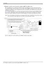
Page 56: ...s an option The Page 65 2 Pneu matic hand interface is required 4 Emergency stop Door switch input The wiring for the safe security of the emergency stop etc is shown in on Page 50 3 6 Emergency stop...

Page 57: ...as the STOP parameter Wait output signal Outputs that the slot is temporarily stopped SLOTINIT Program reset input signal Resets the wait state E Program selection enabled output signal Outputs that t...

Page 58: ...e jog mode Jog mode output 2 bit Outputs the current jog mode JOG Jog feed side for 8 axes Requests the side jog operation None JOG Jog feed side for 8 axes Requests the side jog operation None HNDCNT...

Page 59: ...alls the ferrite core Install the ferrite core in less than 30cm from the contact button You should always connect doubly connection of the emergency stop the door switch and the enabling switch Conne...

Page 60: ...Pin allotment of EMGIN and the EMGOUT connector is shown in Fig 3 13 Within 300mm EMGIN The emergency stop input line from external equipment The emergency stop output line to external equipment Ferr...

Page 61: ...Add axis contacts control output AXMC1 EMGIN pin arrangement AWG 24 18 0 2 0 75mm2 Type 2 1871940 1 EMGIN2 EMGIN1 11A 10A 9A 8A 7A 6A 5A 4A 3A 2A 1A 11B 10B 9B 8B 7B 6B 5B 4B 3B 2B 1B EMGOUT pin arra...

Page 62: ...P shown in Page 54 Fig 3 14 Connection of the special stop input Table 3 4 Special stop input electric specification Item Specifications Internal circuit Type DC input No of input point 1 Insulation m...

Page 63: ...rrently stuck on the connector and connect Minus driver plug area Electric wire plug area AWG 24 18 The connector connection method The electric wire skins covering 7mm In the condition that the minus...

Page 64: ...ot s servo power can be immediately cut only by switch operation of the enabling device 1 servo off and the safety increases To use the robot safely please be sure to connect the enabling device 1 Whe...

Page 65: ...witch input does not matter 2 Jog operation Note3 Note3 Jog operation if door switch input is set for Close Door Close must be performed outside the safety bar rier Manual Enable ON Open OFF Close Doo...

Page 66: ...for additional axes inside the controller and shows a connection example con figuration example The magnet contactor control connector for additional axes AXMC1 is designed to accom modate circuit con...

Page 67: ...SSCNET CN1B OPT CE Servo amplifier Servo amplifier SSCNET cable SSCNET cable CN1A connector CN1A connector OPT connector CN1B connector CN1B connector Cap Magnetic contact It cannot communicate if co...

Page 68: ...tional axis interface Instruction Manual for details on the additional axis function Note1 you use the addition axis function as a user mechanism who became independent of the robot arm please do not...

Page 69: ...series EMGOUT Reference The connection method of the electric wire is the same as connection of the emergency stop Please refer to Page 50 3 6 1 Connection of the external emergency stop EMGOUT connec...

Page 70: ...r needs User installation is required for the options Options come in two types set options and single options 1 Set options A combination of single options and parts that together form a set for serv...

Page 71: ...s The following modes are entered according to the switch state a Not pressed The robot does not operate b Pressed lightly The robot can be operated and teaching is possible c Pressed with force The r...

Page 72: ...cted to the T B connector on the front of the controller Note The connector may be felt hard if installation and removal of the teaching pendant or the dummy plug is repeated to the frequent Enable Di...

Page 73: ...ecelerates the robot to a stop 9 OVRD OVRD key Change moving speed Speed goes up by OVRD key Speed goes down by OVRD key 10 JOG operation key Move the robot according to jog mode And input the numeric...

Page 74: ...8 points expansion 2A RZ375 Source type 0 1 Item Specification Internal circuit Type Transistor output Sink type Source type GRn GR1 GR8 No of output points 8 Insulation method Photo coupler insulatio...

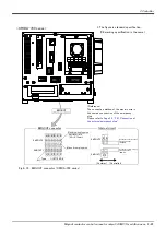
Page 75: ...efer to separate Instruction Manual Controller setup basic operation and maintenance for details on the installing method Fig 3 22 Installation of the pneumatic hand interface CR1DA 700 series A CNHND...

Page 76: ...ications 1 The CR1DA 700 series controller can connect this one interface Table 3 12 Electrical specifications of input circuits Part name Type Qty Mass kg Note1 Note1 Mass indicates one set Remarks P...

Page 77: ...es together with parallel input and output unit 2A RZ361 2A RZ371 please do not overlap with the station number of the parallel input and output interface Item Specification Internal circuit Type Tran...

Page 78: ...yout of connector Fig 3 24 Pin layout of connector CR1DA 700 series SLOT1 Controller rear The figure isstandard specification CE marking specification is the same 1B 1A 20A 20B 1D 1C 20C 20D Connector...

Page 79: ...input and output interface installed in SLOT1 and signal number allocation are shown in Table 3 15 and Table 3 16 Slot numberNote1 Note1 In case of the CR1DA controller the available slot is only SLO...

Page 80: ...Black d General purpose output 2 Error occurring output signal Note2 19C Yellow Red d General purpose input 1 Servo OFF input signal Note2 19D Yellow Black d General purpose output 1 In servo ON outpu...

Page 81: ...24 VDC must be prepared by the customer 60mA 24 12V Output Fuse 0V COM QX41 Mitsubishi programmable controller QY41P Mitsubishi programmable controller 24V COM X Y 24V Input Parallel I O interface Ou...

Page 82: ...nnector 2 are 1A 2A 20A 1B 2B 20B Part name Type Qty Mass kg Note1 Note1 Mass indicates one set Remarks External I O cable 2D CBL 1 pc 0 7 5m 1 84 15m 5m or 15m Items Specifications Number of cables x...

Page 83: ...ector pin numbers and cable colors when making the connections Fig 3 25 Connections and outside dimensions Eg Pin number color indication Orange Red Type of dot mark see figure below Color of dot mark...

Page 84: ...th the power connection cable DCcable 2 A separate 24V power supply is required for the input output circuit wiring Table 3 23 Electrical specifications of input circuits Part name Type Qty Mass kg No...

Page 85: ...ge 12VDC 24VDC Rated load voltage range 10 2 to 30VDC peak voltage 30VDC Max load current 0 1A point 100 Leakage current at OFF 0 1mA or less Max voltage drop at ON 0 9VDC TYP Note1 Note1 The maximum...

Page 86: ...tor Pin No RIO1 2 100 TXRXH TXRXL SG GND List of parts and manufacturer Type Connector type Contact type Resistant Manufacturer NETcable 1 1 178288 3 2 175218 3 6 AMP DCcable 2 2 178288 3 1 175218 3 3...

Page 87: ...d at the time of shipment Fig 3 27 Installing the parallel I O unit CR1DA 700 series 6 0 54 6 150 6 156 2 6 168 12 8 1 7 5 100 4 0 2 A R Z 3 6 1 2 A R Z 3 6 1 6 CR1DA 700 series RIO Controller rear up...

Page 88: ...le DCIN connector RIO2 connector DCIN connector R TM terminator I O unit the bottom connecta layout Connect the NET cable 1 to the RIO connector on the back of the controller Each unit is connected to...

Page 89: ...15 Output 0 to 15 Input 16 to 31 Output 16 to 31 2nd set 1 Input 32 to 47 Output 32 to 47 Input 48 to 63 Output 48 to 63 3rd set 2 Input 64 to 79 Output 64 to 79 Input 80 to 95 Output 80 to 95 4th set...

Page 90: ...ral purpose output 12 11 Orange Red C General purpose output 9 36 Orange Blue C General purpose output 13 12 Gray Red C General purpose output 10 37 Gray Blue C General purpose output 14 13 White Red...

Page 91: ...purpose output 28 11 Orange Red C General purpose output 25 36 Orange Blue C General purpose output 29 12 Gray Red C General purpose output 26 37 Gray Blue C General purpose output 30 13 White Red C G...

Page 92: ...VDC must be prepared by the customer 60mA 24 12V Output Fuse 0V COM QX41 Mitsubishi programmable controller QY41P Mitsubishi programmable controller 24V COM X Y 24V Input Parallel I O interface Outpu...

Page 93: ...ne set Remarks External I O cable 2A CBL 1pc 0 7 5m 1 84 15m 5m or 15m Items Specifications Number of cables x cable size 50 pairs x AWG 28 Total length 5m or 15m Pin no Cable colors Pin no Cable colo...

Page 94: ...eath Type of dot mark A type B type C type D type E type F type G type H type I type J type Dot pattern Receptacle type PCB side 57AE 40500 21D D8 Plug type cable side 57YE 30500 2 D8 DDK Maker DDK 26...

Page 95: ...Personal computer cabe connection Part name Type Qty Mass kg Note1 Note1 Mass indicates one set Remarks Personal computer cable for PC AT 2D 232CBL03M 1pc 4 3m D SUB 9 pin Robot controller side signal...

Page 96: ...e 2D TZ576 1 0 4 Manual BFP A8701 1 Ferrite core E04SR301334 2 Be sure to install this for noise countermeasure Cable clamp AL4 2 AL5 2 Part name Type Qty Remarks Master station QJ61BT11 Q series 1 FX...

Page 97: ...c setup 1 2 4 8 Maximum link point Remote I O RX RY Each 896 points The two last cannot be used Remote register RWr RWw Each 128 register 16 bits register Extended cyclic setup 1 fold setup 2 fold set...

Page 98: ...card as it is embedded in the robot controller can only be mounted into slot 2 Easy wiring since only four terminals need to be connected Dedicated commands have been added to MELFA BASIC V robot prog...

Page 99: ...memory cassette 2D TZ454 1 0 1 Items Specifications Remarks External dimensions Approx 94 W X65 D X15 H mm Excluding the connection connector Mass Approx 0 2 kg Connection method Connection using a sp...

Page 100: ...e Windows standard is used for windows operation so the controller initialization and startup operations can be carried out easily by following the instructions given on the screen Even a beginner can...

Page 101: ...tax check Command template Position conversion batch editing Position variable template Print print preview Control func tions Program file control list copy movement delete content compari son name c...

Page 102: ...790 Specification of the robot arm and controller Robot Arm Setup Maintenance BFP A8791 Installation method of the robot arm jog operation and maintenance and inspection procedures Controller Setup Ba...

Page 103: ...confirm the part name robot arm and controller serial No and purchase the parts from your dealer Table 3 42 Controller consumable parts list No Name Type Note1 Note1 Confirm the robot arm serial No an...

Page 104: ...el 50 80 Automatically adjusts the acceleration deceleration according to the parameter setting value Oadl ON ets the hand and work conditions for automatic adjustment of the accel eration deceleratio...

Page 105: ...executed when an interrupt is generated from the communication line On Com 1 GoSub L100 Enables the interrupt from the communication line Com 1 On Disables the interrupt from the communication line Co...

Page 106: ...nt variable Def Jnt TAIHI Defines the position variable Def Pos TORU Defines the function Def FN TASU A B A B Clear Clears the general purpose output signal variables in program variables between prog...

Page 107: ...ints can be designated and that area set as the outside operation range Furthermore a signal can be output when the axis enters that area Up to 32 types of area can be designated AREA1CS AREA32CS Spec...

Page 108: ...t set Communication setting CBAU232 Set the baud rate CLEN232 Set the character length CPRTY232 Set the parity CSTOP232 Set the stop bit CTERM232 Set the end code Slot table SLT1 SLT32 Make settings p...

Page 109: ...red to operate the robot arm unpacking transportation installation confirmation of operation and the maintenance and inspection procedures Explains the procedures required to operate the controller un...

Page 110: ...nstruction manuals 5Instruction Manual Explains the detailed description of data configuration of shared memory monitoring and operating procedures about the GOT CRnD 700 series controller Extended Fu...

Page 111: ...nd the error exceeds the specified amount The drive circuit is shut off The robot stops and an alarm displays 5 AC power voltage drop diagnosis function Activates when the AC power voltage drops below...

Page 112: ...ations maintenance and safety required for the robot work Only trained and registered operators must operate the robot Participation in the Special training for industrial robots sponsored by the Labo...

Page 113: ...ely stop the robot operation when trouble occurs 7 The teaching operator must have completed special training regarding safety Training regarding industrial robots and work methods etc 8 Create signal...

Page 114: ...f explanation there is the section different from the product Also refer to Page 52 Fig 3 13 External emergency stop connection Wiring example 1 Connect the emergency stop switch of peripheral equipme...

Page 115: ...heral equipment Connect the power supply of peripheral equipment by the polarity shown in the figure 3 5A 5B and 6A 6B terminal of EMGIN is short circuited at factory shipments Remove it and connect w...

Page 116: ...h the compulsive guide 5 The emergency stop button of the robot controller operation panel 6 The emergency stop button of T B connected to the robot controller 7 Emergency stop input relay 8 Refer to...

Page 117: ...pments Remove it and connect the emergency stop switch and power supply of peripheral equipment Connect the power supply of peripheral equipment by the polarity shown in the figure 3 5A 5B and 6A 6B t...

Page 118: ...5 Cable length The length of the wire between the switch and terminal block must be max 15m or less Please use the shield line in case of the cable may receive the noise etc by other equipment such a...

Page 119: ...er dust and oil mist present 6 3 Precautions for handling 1 RV 2SD has brakes of J2 J3 and J5 axes RV 2SDB has brakes of all axes The precision of the robot may drop looseness may occur and the reduct...

Page 120: ...unit to the primary power source in order to reduce interference 13 Do not conduct an insulated voltage test If conducted by mistake it may result in a breakdown 14 Fretting may occur on the axis whic...

Page 121: ...VD01 1E VD01E 1E VD02 1E VD02E Not provided E VD01 E VD01E Not provided E VD02 E VD02E Hand input cable 1S HC30C 11 Not provided Provided Hand output cable 1E GR35S Not provided Provided Hand curl tu...

Page 122: ......

Page 123: ......

Page 124: ......

Page 125: ......

Page 126: ......

Page 127: ......

Page 128: ......

Page 129: ......

Page 130: ......

Page 131: ......

Page 132: ......

Page 133: ......

Page 134: ......

Page 135: ......

Page 136: ......

Page 137: ......

Page 138: ......

Page 139: ......

Page 140: ......

Page 141: ......

Page 142: ......

Page 143: ......

Page 144: ......

Page 145: ......

Page 146: ......

Page 147: ......

Page 148: ......

Page 149: ......

Page 150: ...without notice HEAD OFFICE TOKYO BUILDING 2 7 3 MARUNOUCHI CHIYODA KU TOKYO 100 8310 JAPAN NAGOYA WORKS 5 1 14 YADA MINAMI HIGASHI KU NAGOYA 461 8670 JAPAN Authorised representative MITSUBISHI ELECTRI...

Reviews: