Mitsubishi Heavy Industries TU85SAE Operation Manual Download Page 33

- 28 -

4 Initial setting

1

5

2

6

3

7

9

4

8

10

5


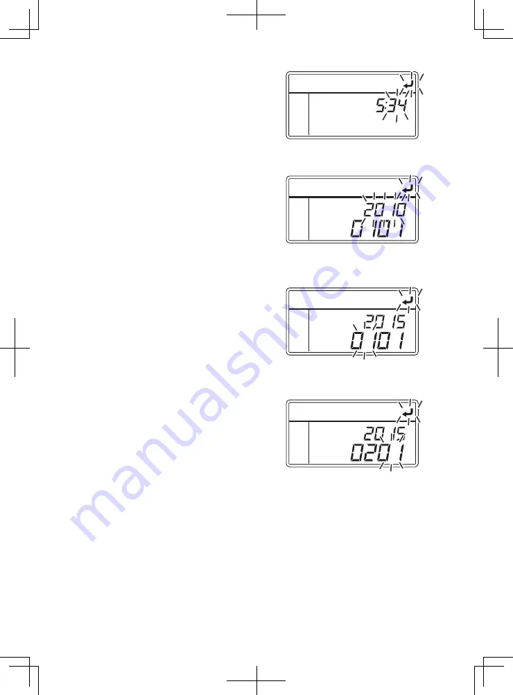
Press the [UP] or [DOWN] switch to 
adjust to the current time (minute).

6


Press the [SET] switch.

⇒ 

Calendar (year) blinks on the digital 
display.


Pressing the [UP] or [DOWN] switch, 
adjust the calendar to the current 
year.

7


Press the [SET] switch.

⇒ 

Calendar (month) blinks on the digital 
display.


Pressing the [UP] or [DOWN] switch, 
adjust the calendar to the current 
month.

8


Press the [SET] switch.

⇒ 

Calendar (date) blinks on the digital 
display.


Pressing the [UP] or [DOWN] switch, 
adjust the calendar to the current 
date.

9


Press the [SET] switch.

⇒ 

Setting is completed, and the display returns to the "Clock/calendar 
display mode".

Summary of Contents for TU85SAE

Page 1: ...to use Mitsubishi Refrigeration Unit safely Operate or service the refrigeration unit only after you have read this manual and understand its contents Carefully store this manual in a fixed place so that it is immediately available for your reference when you need it YEAR 2016 TSJ012A204A OPERATION MANUAL OPERATION MANUAL ...

Page 2: ...vent it from getting damaged We are not able to foresee all potential risks of this refrigeration unit or dangers due to mishandling by the customers Therefore it is necessary to take measures for safety in addition to the items described in this manual or on warning labels For the following works contact your nearest dealer If those works were carried out by customer the refrigeration unit may lo...

Page 3: ...sent with our company This manual also contains the explanation of optional specification The contents of this operation manual may differ from that of the refrigeration unit used by a customer due to specification change The contents described in this operation manual may be changed without a prior notice When transferring or lending the refrigeration unit attach this operation manual together wi...

Page 4: ...nd specification change 16 Power supply equipment 16 Emergency measure 17 Handling of warning labels 19 Prevention of start during inspection work 21 Clothing and protective equipment 21 Handling of grease and oil 21 When abnormal conditions are detected 21 For emergency 21 4 Initial setting 22 Mode displays and functions 22 Outline of the user setting mode 25 Setting the clock calendar 27 Setting...

Page 5: ...y 58 Inspection of leakage and wiring condition 58 Inspection of condenser coil 59 Periodic inspection 60 Periodic inspection check sheet 61 Details of applicable oils and cooling water 63 Power supply system 63 8 Operation or stop for long period of time 64 When operating at a low inside container temperature for a long period of time 64 When stopping the refrigeration unit for a long period of t...

Page 6: ...ing during cooling operation and to prevent refrigerating power from decreasing There are following 2 methods to start defrosting operation 1 Automatic defrosting operation Defrosting starts automatically by the timer setting Refer to page 29 for defrosting timer setting 2 Manual defrosting operation Defrosting starts forcibly by pressing the switch of controller Refer to page 42 for how to operat...

Page 7: ...et starting time and stopping time of the operation Refer to pages from 43 to 46 for how to set 6 Self diagnosis operation function PTI Pre Trip Inspection operation This is the function to diagnose the refrigeration unit automatically if it has any trouble or not Refer to pages from 47 to 48 for how to operate ...

Page 8: ...unit 7 Fuel pump 3 Control box 8 Fuel tank 4 Refrigerant piping 9 Water separator 5 Battery 5 9 6 8 7 1 2 3 4 Actual locations of above units etc should be checked beforehand because they could vary depending on vehicle models or other Arrangement plan for main parts Single specification TU85SAE ...

Page 9: ... 4 8 1 0 Evaporator unit Single specification TU85SAE 1 Supply air outlet for evaporator 4 Evaporator coil 2 Electric heater Optional 5 Electronic expansion valve 3 Evaporator fan motor A 1 5 4 2 3 Inside of view A Thin type TU100SAE EVX ...

Page 10: ...E CNF 1 Front panel 10 Motor 2 Commercial power socket 11 Dryer 3 Latch 12 Oil filter 4 Reservoir tank 13 Fuel filter 5 Compressor 14 Air cleaner 6 Alternator 15 Control box 7 Engine 16 Main switch 8 Radiator condenser 17 Label F Gas 9 Sight glass 1 15 2 3 4 5 6 7 16 14 13 12 11 10 9 8 17 ...

Page 11: ...igeration unit is stopped 3 UP switch Changes the setting temperature setting screens and setting values 4 DOWN switch Changes the setting temperature setting screens and setting values 5 SET switch Registers the setting 6 WHISPER switch Selects the normal operation or whisper operation 7 DEFROST switch Starts the manual defrosting operation 8 Digital display area Displays the inside container tem...

Page 12: ...r a remote control device etc Display for timer The lamp blinks when the display or setting for timer operation is made Display for self diagnosis operation PTI Refer to page 47 The lamp lights during self diagnosis operation Display for defrosting The lamp blinks when the display or setting for defrosting operation is made Display for Whisper operation The lamp lights when Whisper operation is se...

Page 13: ...6 Operation status icon These lamps light depending on the status of operation or setting Display for operation The lamp lights during operation including during thermostat OFF Display for heating operation The lamp lights during the heating operation Display for cooling operation The lamp lights during the cooling operation Display for setting temperature The lamp lights when displaying the setti...

Page 14: ...orking nearby c Front panel The cover prevents operators from contacting with the rotating part during operation d Front panel opening detection switch When the front panel is opened for inspection for example this switch detects it and stops the start of engine or motor Refer to page 54 People who handle this refrigeration unit are requested to understand the functions of these protective devices...

Page 15: ...le will result in death injury or serious accident such as damage of the refrigeration unit Indicates dangerous situation which if mis handled will result in death serious injury and serious accident such as damage of the refrigeration unit Indicates potentially dangerous situation which if mis handled will result in minor injury or moderate property damage Symbols Symbols Description Symbols Desc...

Page 16: ...s running WARNING Do not place combustible materials in the vicinity of muffler and exhaust pipe Do not park on the area where combustibles such as falling leaves accumulate on Otherwise it may cause a fire because muffler and exhaust pipe will be hot Do not start the engine in poorly ventilated places such as an indoor parking lot Otherwise it may cause carbon monoxide poisoning due to exhaust ga...

Page 17: ...y deteriorate quality of the cargo if it is used for any other purpose Use specified fuel engine oil compressor oil and cooling water Refer to page 63 Otherwise it may cause troubles if any other materials are used During and after the operation WARNING Make sure that the front panel of condensing unit is closed before starting operation Otherwise it may cause accidents CAUTION Do not touch the mu...

Page 18: ...not to drink them by mistake Otherwise it may cause health disorders such as frostbite loss of eyesight and pneumonia Do not wash the refrigeration unit with a steam washer or a high pressure washer Otherwise it may cause a rupture due to pressure rise in the refrigeration unit or distortions of the condenser fin When inspecting or cleaning the refrigeration unit stop the unit by turning the Main ...

Page 19: ...o inside container temperature rise Waterproof the cargos if they need to be Water may drip or splash from the evaporator unit Handling of electric equipment and power codes WARNING Do not directly splash water on the electric equipment or wash them with water Never touch the electric equipment such as power plug and so on or operate the switches with wet hands Do not modify the power code or appl...

Page 20: ...ode Check the plug of the power code for dust If there is no dust insert it firmly Surely protect the power socket with a cover when it is not used When the cover is damaged repair it immediately Otherwise it may cause an electric shock or a fire due to the heat breaking of wire and leaking of water etc CAUTION Do not start and stop the operation with pulling out or inserting the power supply brea...

Page 21: ...efrigeration unit and specification change WARNING Do not modify the refrigeration unit or change the specification It may cause a serious accident if customer modify the refrigeration unit or change the specification by himself herself Power supply equipment WARNING Be sure to earth the power supply equipment to supply the electricity to the refrigeration unit It may cause an electric shock if th...

Page 22: ...m her to a physician as soon as possible When swallowing refrigerant Do not throw up by force and consult a physician as soon as possible Precautions for physician Use of Catecholamine system medicine such as adrenaline and so on may cause heart arrhythmia Therefore it is required to use only for the emergency life sustaining treatment with special consideration 2 Compressor oil When compressor oi...

Page 23: ...rated gas When someone inhaled the gas a lot move to the place with fresh air immediately holding him her with a blanket or the like to keep warm Then consult a physician if it is necessary When he she breathes irregularly or feels sick consult a physician immediately When swallowing antifreeze coolant Throw it up immediately and consult a physician as soon as possible When inside the mouth is con...

Page 24: ...ant precautions are stated on the warning labels Never operate the refrigeration unit unless fully understanding the meanings of the warning labels When you found some difficulties to understand contact your nearest dealer b Always keep the labels in good condition to read Do not peel off tear off or damage the labels or do not wipe with solvent or paint them c When the labels become illegible pur...

Page 25: ...n for safety 1 5 2 6 3 7 9 4 8 1 0 Front view Front view inside Back view TLB011H005G PSA011H011 PSA011H011 TSJ011H022 PSA011H011A TSJ011H023A TSJ011H072N BSA011H009F PSA011H011A PSA011H011A SSA011C149F Control box 98 ...

Page 26: ...nt it from getting rolled in Fasten the cuffs firmly Handling of grease and oil As for the measure how to handle or dispose the fuel engine oil and antifreeze coolant and so on to be used for this refrigeration unit follow the precautions stated on each product These are harmful to human body or environment when mishandling them When abnormal conditions are detected Refer to 9 For emergency when a...

Page 27: ... switch UP switch DOWN switch UP switch DOWN switch UP switch UP switch DOWN switch UP switch DOWN switch UP switch DOWN switch UP switch DOWN switch UP switch DOWN switch DOWN switch UP switch Normal display screen Clock calendar display mode Refer to page 27 Current error display mode Refer to page 65 Operation time cycles display mode Refer to page 30 Operation pattern selection mode Refer to p...

Page 28: ...6 Printer output setting mode Mode to print temperature history data An optional printer is necessary to print graphic data Option Defrost interval timer setting mode Mode to display and set the defrost interval timer The time is displayed in hour Initial setting before shipment is 6 hours Refer to page 29 ON timer setting mode Mode to set the time to start the operation of the refrigeration unit ...

Page 29: ...ctions related to the controller operability and others Refer to page 25 Operation time start stop cycles display mode Mode to display the operation time or number of start stop cycles of each device Refer to page 30 Fuel circulation mode Mode to circulate fuel forcibly in order to supply fuel to the engine and also to purge air trapped in the fuel system Refer to page 32 ...

Page 30: ... The same occurs also when the setting change is aborted on the way User setting mode Automatic drive selection backup setting mode Minimum power operation time setting mode DOWN switch UP switch Minimum power stop time setting mode Celsius Fahrenheit display setting mode DOWN switch UP switch DOWN switch UP switch Maximum power stop time setting mode Out of adequate range temperature setting mode...

Page 31: ...peration setting mode DOWN switch UP switch DOWN switch UP switch Operation log interval setting mode In stop log interval setting mode When it is necessary to change the setting of LCD backlight buzzer sound or logging interval consult your nearest dealer DOWN switch UP switch Option selection setting mode UP switch DOWN switch UP switch DOWN switch ...

Page 32: ...he Clock calendar display mode 2 Press the SET switch Time hour starts to blink on the upper digital display Icon blinks 3 Press the UP or DOWN switch to adjust to the current time Hour NOTE The clock shows the time up to 24 hours Set 19 00 if it is 7 o clock PM 4 Press the SET switch The time minute in the digital display area starts to blink ...

Page 33: ...t the calendar to the current year 7 Press the SET switch Calendar month blinks on the digital display Pressing the UP or DOWN switch adjust the calendar to the current month 8 Press the SET switch Calendar date blinks on the digital display Pressing the UP or DOWN switch adjust the calendar to the current date 9 Press the SET switch Setting is completed and the display returns to the Clock calend...

Page 34: ...t interval timer setting mode Right figure 3 Press the SET switch Time starts to blink on the lower digital display Icons and starts to blink 4 Press the UP or Down switch to select the setting time NOTE The defrost interval time can be selected from 12 steps ranging from 1H 1 hour at the minimum to 12H 12 hours at the maximum 5 Press the SET switch Setting is completed and the display returns to ...

Page 35: ...t figure 3 Press the SET switch The digital display changes to the engine operation time for engine oil inspection mode Icon starts to blink if the maintenance request time has been reached 4 Hold down the SET switch If you release hand it returns to the original display The current engine operation time for engine oil inspection is displayed on the digital display The lower digital display is up ...

Page 36: ...p cycles SV5 solenoid valve start stop cycles EEV A on off cycles DH A operation time Hot water pump operation time WSV A solenoid valve start stop cycles EH A operation time Evaporator fan 1 operation time Evaporator fan 2 operation time Evaporator fan 3 operation time Evaporator fan 4 operation time Engine operation time Motor operation time Cooling water belt operation time Cooling water workin...

Page 37: ...h to select 5 Press the SET switch The display changes to show the fuel circulation on and the remaining time in minute alternately at each 2 seconds Fuel circulation is completed 10 minutes later and the display returns to the Normal display screen 22 page To interrupt the fuel circulation press the mode switch to return to the Fuel circulation mode NOTE If fuel is used up air may intrude in the ...

Page 38: ...electric devices such as power plug and so on with wet hands Otherwise it may cause an electric shock Operate the refrigeration unit with motor drive when operating it indoor The place must be well ventilated when operating it with engine drive Otherwise it may cause oxygen deficiency due to exhaust gas NOTE Be sure to carry out the self diagnosis operation PTI operation before the operation ...

Page 39: ...8 1 0 Power on Main switch Front panel Condensing unit 1 Open the front panel of condensing unit Refer to page 54 2 Turn the Main switch which is located at the right side of control box to ON 3 Close the front panel Refer to page 54 ...

Page 40: ...s operated with the motor Operating with the motor WARNING Use 4 core cabtyre cables conductor cross section with 5 mm2 or more for power cable Do not connect it to extension code Use MENNEKES Part no 6 400V 32A for power supply plug Otherwise it may cause an electric shock or a fire due to the heat and breaking of wire CAUTION Use 3 phase AC400V 50Hz for power supply It may cause damage of the re...

Page 41: ...ration pattern selection mode Right figure 3 Press the SET switch It is changed to the operation pattern selection setting mode on the LCD display 4 Press the UP or DOWN switch to select the automatic start stop operation or the continuous operation Automatic start stop operation At the shipment Continuous operation 5 Press the SET switch Selection is completed and the display returns to the Opera...

Page 42: ...ON The action that the operation re starts automatically when the inside container temperature goes beyond the designated range of the setting temperature during thermostat OFF Run Run Stop Stop Run Stop Automatic start stop operation High Low Time Setting temperature Inside container temperature Inside container temperature What is the continuous operation The refrigeration unit operates without ...

Page 43: ...arning buzzer sounds before the engine or motor starts to run Operation starts with the selected drive engine or motor and operation pattern automatic start stop operation or continuous operation NOTE The refrigeration unit will not start while the front panel of condensing unit is open because the safety device is tripped Error code is displayed If you close the front panel the unit starts to ope...

Page 44: ...ting operation for 10 to 20 seconds During the device protecting operation is displayed on the upper digital display while is displayed on the lower digital display If all steps of operation stop are completed the controller is turned off automatically NOTE When the motor operation stops the buzzer sounds and is displayed on the LCD display in order to prevent failure to disconnect the power plug ...

Page 45: ...ital display starts to blink 3 Press the UP or DOWN switch to change the temperature NOTE Each press on the UP switch increases the value by 0 5 while each press on the DOWN switch decreases the value by 0 5 In case of Fahrenheit by 1 Keeping pressing either switch changes the value continuously 4 Press the SET switch The setting is completed and the screen returns to the Normal display screen Ref...

Page 46: ...cted the setting is reset If you need the whisper operation you have to press the WHISPER switch at each time when the operation is started NOTE The whisper operation is the function to run the engine at the slow speed revolution only Use this function when it is necessary to suppress the sound of unit operation temporarily during stopping time of the vehicle and so on The setting can be changed s...

Page 47: ... the defrost operation stops the refrigeration unit returns to the cooling operation If you need to interrupt the defrost operation and return to the cooling operation press the DEFROST switch once more If the RUN STOP switch is turned OFF the defrost operation is interrupted and the refrigeration unit stops NOTE Manual defrost operation can be started even during the unit stop by thermostat off M...

Page 48: ...ss the UP or DOWN switch until the display changes to the ON timer setting mode Right figure 3 Press the SET switch or starts to blink on the upper digital display Icons and start to blink 4 Press the UP or Down switch to select NOTE or is displayed alternately by pressing the UP and DOWN switch When OFF timer setting is not to be set or to be cancelled select ...

Page 49: ...8 Press the UP or DOWN switch to adjust to the ON timer setting time minute 9 Press the SET switch The setting is completed and the display returns to the Setting the ON timer NOTE When performing the timer operation with the motor drive confirm that the commercial power supply is connected to the refrigeration unit When the ON timer operation is selected take note that the refrigeration unit star...

Page 50: ...ess the UP or DOWN switch until the display changes to the OFF timer setting mode Right figure 3 Press the SET switch or starts to blink on the upper digital display Icons and start to blink 4 Press the UP or Down switch to select NOTE or is displayed alternately by pressing the UP and DOWN switch When ON timer setting is not to be set or to be cancelled select ...

Page 51: ... 24 hours Set 19 00 if it is 7 o clock PM 7 Press the SET switch The setting time minute starts to blink 8 Press the UP or DOWN switch to adjust to the OFF timer setting time minute 9 Press the SET switch The setting is completed and the display returns to the Setting the OFF timer NOTE When the OFF timer operation is selected take note that the refrigeration unit stops the operation automatically...

Page 52: ...er supply is not connected Starting the operation 1 Press the MODE switch when the refrigeration unit is stopped The controller becomes activated and the display changes to the Normal display screen NOTE Go to the procedure 2 while the refrigeration unit is operating 2 Press the MODE switch The display changes to the Clock calendar display mode 3 Press the UP or DOWN switch until the display chang...

Page 53: ...ion unit stops temporarily The self diagnosis operation starts and the step No is shown on the lower digital display When the diagnosis is completed the engine stops and the result of diagnosis will be displayed Finishing the operation when no defects are detected 7 When no abnormal condition has been detected is displayed on the lower digital display 8 Press the RUN STOP switch to turn it OFF The...

Page 54: ...ated temperature with other refrigeration device in advance 2 Clean inside of the container 3 Perform the inspection of the refrigeration unit and the body Refer to page 52 Check with the body manufacturer for the items to be inspected 4 Set the right temperature for transportation of the cargo and cool down or heat up inside of the container to the setting temperature Refer to page 40 NOTE The te...

Page 55: ...orator Lower than supply air outlet More than 100 mm 50 75 mm More than 30 mm More than 30 mm Supply air outlet 3 Keep the top layer of the cargo as flat as possible CAUTION Waterproof the cargoes if they need to be Water may drip or splash from the evaporator unit 4 When transporting any cargo to be protected from water damage cover the cargo placed under the evaporator unit or near its outlet wi...

Page 56: ...es on the evaporator coil while the refrigeration unit is operated during loading or unloading Since the inside container temperature rises or falls during cold winter while the door is kept opened load or unload as quickly as possible A curtain helps to prevent ambient air from entering or inside air from escaping during loading or unloading ...

Page 57: ...ak out it stays around the refrigeration unit and may catch a fire Do not modify or remove the protective device installed on the front panel of condensing unit It may cause injury if the refrigeration unit is operated with the front panel of condensing unit opened Be sure to perform daily and periodic inspections Otherwise it may cause troubles of the refrigeration unit or accidents The area must...

Page 58: ...iately Otherwise it may cause blindness or frostbite Stop the operation and wait until engine and others are cooled down before performing the inspection Since the engine exhaust pipe refrigerant pipe or the like become very hot it may cause burns if you touch them Set the Main switch to OFF to stop the refrigeration unit and disconnect battery terminals and the power cord plug during inspection O...

Page 59: ...stay in the mounting hole on the back of front panel to fix the panel Fixing angle of front panel can be selected from 2 steps 90 and 135 Closing the front panel of condensing unit 1 Remove the stay and close the front panel 2 Push the latches at both sides in and close the front panel It is locked 3 Confirm that the front panel is locked completely NOTE Unless the front panel is pushed in firmly ...

Page 60: ...ll it immediately after the engine stopped High temperature steam may blow out and it may cause heat injury Use the designated antifreeze coolant Otherwise it may cause troubles 1 Check that the fluid level is between MAX and MIN in the reservoir tank 2 When the fluid level is lower than MIN refill the designated antifreeze coolant to the level of MAX Refer to page 63 for the designated antifreeze...

Page 61: ...essor belt Detail of water pump belt Compressor belt Water pump belt Water pump Engine 1 Visually inspect the compressor belt and the water pump belt for defects such as scratch crack or one sided wear etc 2 Check the moving sections for interference with other parts NOTE When there is any abnormal condition or any slack of the belts surely contact your nearest dealer ...

Page 62: ...ngine oil during refilling If the oil is heated up it may cause a fire 1 Check if the fluid level of engine oil is in the vicinity of the upper limit of the oil level gauge Tighten the screw of oil level gauge firmly to check 2 When the quantity of engine oil is not enough supply the designated engine oil from the oil inlet to the level not to excess the upper limit Refer to page 63 for the design...

Page 63: ...d fuel NOTE Stop the operation with the Operation switch when refueling When fuel has run out select the fuel circulation mode Refer to 34 page to supply fuel to the engine and also to purge air from the fuel system before starting operation Inspection of leakage and wiring condition 1 Check if there is no leakage of cooling water engine oil or engine fuel from the tanks pipes or connecting parts ...

Page 64: ...it Clean the coil at regular intervals Cooling water piping and engine fuel piping in the condensing unit Engine fuel piping and battery wiring Cooling water inlet Radiator condenser Reservoir tank Air vent valve Fuel hose Fuel filter Engine Water drain cock Cable Battery Driving direction Chassis earth bolt Fuel hose Fuel pump Fuel hose Fuel outlet pipe joint Fuel tank Fuel tank return oil pipe j...

Page 65: ...n to ensure to use the refrigeration unit in the best condition all the time Periodic inspection consists of the following items 1 Inspection at every 1000 hours 2 Inspection at every 3000 hours 3 Inspection at every 9000 hours Check the contents of inspection with the check sheet submitted after the periodic inspection ...

Page 66: ...and leakage of cooling water Water hose radiator water pump Engine speed Color degree of flush in refrigerant sight glass Replacement of air cleaner Replacement of engine oil 100 hours at initial inspection only Replacement of oil filter 100 hours at initial inspection only Refil of cooling water Governor lever link and related parts of engine Cleaning of fuel tank Cleaning of fuel pump Replacemen...

Page 67: ...of evaporator coil Cleaning of water drain port Damage on rubber cushion Replacement of cooling water Or for 2 years Replacement of centrifugal clutch shoe Valve clearance Replacement of glow plug Or 30000 cycles Replacement of starter Or 30000 cycles Replacement of stop solenoid Or 30000 cycles Overhaul of engine Injection nozzle injection pump Replacement of compressor belt Replacement of electr...

Page 68: ... coolant quantity L 1 4 1 6 1 8 2 1 2 3 2 5 2 8 Lowerst ambient temperature C 10 15 20 25 30 35 40 Initial setting Antifreeze coolant concentration 50 wt NOTE Adjust antifreeze coolant concentration according to the expected lowest ambient temperature If it is not appropriate the cooling water may be frozen and cause the damage of the radiator or engine As the cooling water is an industrial waste ...

Page 69: ...ation unit once or twice every week and open up the door on the vehicle body to return the inside of container to ordinary temperature and melt grown ice CAUTION Park the vehicle at a flat place and operate the refrigeration unit Otherwise the evaporator becomes unable to drain and water overflows in the container damaging cargoes with water When stopping the refrigeration unit for a long period o...

Page 70: ...Switching Normal display and Current alarm display Switching from Normal display screen to Current alarm display mode Press once each on the MODE switch and UP switch The display returns to the Normal display screen 10 seconds later Extending Current alarm display mode Press the SET switch on the Current alarm display mode screen Switching from Current alarm display mode to Normal display screen P...

Page 71: ...itch to OFF then disconnect the battery terminal and plug for power code to change the fuse Otherwise it may cause injury or an electric shock due to unexpected start Fuses are mounted in the control box of condensing unit Single specification TU85SAE F2 F4 F9 F8 F7 F6 F5 F12 F11 F1 F10 F3 F11 F12 F10 F3 F1 fuse holder F1 20 A operation circuit is fixed with the fuse holder F2 15 A Relay circuit F...

Page 72: ...an emergency stop If a remark Automatic operation resume is written in the column for the Unit Condition in the list of alarm codes the operation will resume as soon as required conditions are satisfied If a remark Unit stops is written in the same column start the operation in usual procedure after removing causes of the troubles Resuming operation after an emergency stop Press the RUN STOP switc...

Page 73: ... the setting value Ask a dealer for inspection Front panel of condensing unit is open Close the panel completely Engine clutch overheat prevention device has tripped Ask a dealer for inspection This alarm cannot be reset because it could result in a fire When this alarm has occurred contact a dealer High pressure switch has tripped 1 Open the front panel and inspect the condenser fan drive system ...

Page 74: ...heck if fuel exists in the fuel tank If fuel exists ask a dealer for inspection Fuse F10 11 or 12 has blown Replace the fuse F10 11 or 12 10 A in the control box If the same trouble persists after replacement ask a dealer for inspection Fuse F4 is blown Replace the blown fuse 10 A in the control box If it persists even after replacement ask your service agent to inspect Abnormal return air tempera...

Page 75: ...id circuit Abnormal starter relay circuit Abnormal motor relay circuit Abnormal pre heater relay circuit Abnormal evaporator electric heater relay Option Abnormal fuel pump Evaporator fan motor fuse has blown Hot water solenoid valve error Optional Hot water pump relay error Optional Abnormal economizer solenoid valve Abnormal engine clutch temperature sensor Battery voltage drop Blinking Blinking...

Page 76: ...9 695 2000 200 744 420 54 Dedicated engine diesel and motor Automatic start stop and continuous operation selection 3TNV76 4 cycle water cooled vertical diesel 1116 2 8 Outdoor 30 C inside container 0 C high speed at shipment 9 5 Oil type Class CE or higher of API classification 10W 30 Diesel fuel Intense cold season cold weather diesel fuel High speed 10 4 2100 low speed 6 9 1500 or more CSA130 O...

Page 77: ......

Page 78: ...TRANSPORTATION REFRIGERATION DEPARTMENT 3 1 ASAHI NISHIBIWAJIMA CHO KIYOSU AICHI 452 8561 JAPAN Phone 052 503 9312 ...

Reviews: