-
292
-
CNA
⑤
CNEEV2
②
CNEEV1
①
CNMAIN
③
Grounding cable (G-1)
Grounding cable (G-2)
Grounding cable (G-2)
Grounding cable (G-1)
〔
Front view
〕
〔
Side view
〕
CN20V
④
CNB
⑤
CNC
⑤
CND
⑤
Disconnect the black cable
Screw
Square hole
Disconnect the white cable
Sub PCB (PCB2) on the lower layer
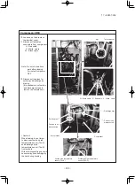
1.After removing the Main PCB,
disconnect all connectors on
Sub PCB.
①
Disconnect the connector
of CNEEV1.
(
for EEVA & EEVB)
②
Disconnect the connector
of CNEEV2.
(
for EEVC & EEVD)
③
Disconnect the connector
of CNMAIN.
(Going to Main PCB)
④
Disconnect the connector
of CN20V.
(Going to Main PCB)
⑤
Disconnect the connectors
of CNA, CNB, CNC and
CND.
2.Loosen screws and disconnect
the grounding cables.
3.Disconnect the fasten
connector of the black cable.
Note : Be sure to do above
work after elapsing
3 minutes from power OFF.
4.Loosen a screw and pull up
the right side of the upper TB
to unlatch from the left side
square hole.
5. Loosen the screw of
N-terminal and disconnect
the white cable.
'17 • SCM-T-225


