


-
95
-
5.1 Installation of indoor unit
(1)
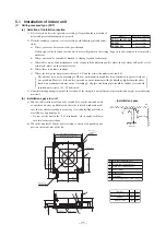
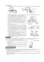
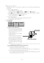
Ceiling recessed type (FDT)
(a)
Selection of installation location
1) Select location where the space above ceiling is larger than those mentioned
below and perfect draining can be assured.
2) With the customer’s consent, select a location with following suitable condi-
tions.
a) Where cool air or hot air can easily pass through.
If the height of the location exceeds 3 m, hot air will gather in the ceiling. Suggest to the customer to also install a
circulator.
b) Where water can be completely drained. A sloping location for drainage.
c) Where there are no wind disturbances to the suction inlet and blowing outlet, where the fire alarm will not be set off
erroneosly, where no short circuits occur.
d) Where there is no direct sunlight.
e) Where the dew point temperature is below 28°C and the relative humidity is below 80%.
The unit has been tested according to JIS dew point conditions and has been confirmed to operate without
any problems. However, if the unit is operated in an environment with the humidity higher than the above
limit, water condensation may occur. Accordingly, all pipes and drain pipes should be further covered with
insulation materials of 10 - 20 mm thick.
3) Consider the supporting strength of the location. If the strength is not sufficient to sustain the unit weight, use reinforcing
materials.
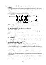
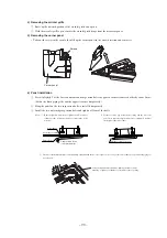
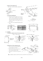
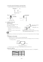
(b) Installation space for unit
a) When a sufficient interval cannot be secured between the unit and a wall
or another unit, shut up diffusers on that side to block winds and make
sure that no short-circuiting is occurring. (A wind blocking material is
available as an optional part)
• Do not use the unit in the “LO” wind mode, when winds are blown
into two or three directions.
b) When the unit has 2500 mm or less clearance, attach a fan guard (option
part) on the intake side of the fan.
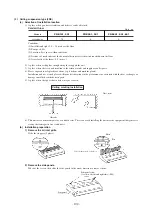
FDT151, 201, 251, 301
FDT401
Model
Space above ceiling (h)
Over 290mm
Over 315mm
FDT501, 601
Over 385mm
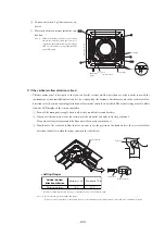
1‚000 or more
(mm)
Obstacle
2‚500 or more
•
Installtation space
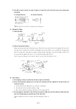
A
B
C
D
E
F
G
Gas tube connecting port
Liquid tube connecting port
Drain line connecting port
Power intake
Hanging bolt
OA intake
Blowout branch duct connecting port
(
)
Model
FDT151, 201, 251, 301
FDT401
FDT501, 601
a
212
212
269
b
270
295
365
Drain hose
(Accessories)
(Local setting)
840
a
95
45
35
b
187
137
332
637
422
420
310
267
D
E
G
B
A
C
860~890
(Ceiling hole size)
Fresh air
opening for
ducting
780
(Suspension bolts pitch)
675
(Suspension bolts pitch)
Control box
Control box
or more
Lug for
suspension bolts
F