


-
82
-
(q)
Using 1 remote controller to control multiple units (indoor units - up to 16 units)
1) Function
A single remote control switch can be used for group control of multiple units (indoor units - up to 16 units). All units in
the group that have had the remote control switch set at [Operating Mode] can be turned on and off in order of the unit
number.
This functions independently of the thermostat and protection functions of each unit.
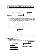
2) Display to remote controller
a) Remote or center and heating preparation:
Displays for the youngest unit for the remote mode (center mode
if there is no remote mode) of the units in operation.
b) Inspection and filter sign:
Displays either to the first corresponding unit.
3) Confirmation of connected units
Pressing the “AIR CON No.” switch on the remote control unit displays the indoor unit address. Pressing the
or
button
displays the indoor units in the order of lowest to highest assigned No.
4) Error
a)
If an error occurs (protection device activation) with some of the units in the group, those units will have an error
stop, but the properly operating units will continue operation.
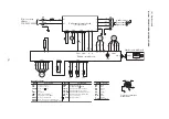
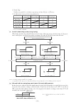
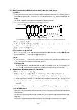
b) Wiring outline
Route the wire connecting each of the indoor and outdoor units as it would be for each unit. Use the terminal block
(X, Y, Z) for the remote control for the group controller and use a jumper wire among each of the rooms.
(r)
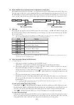
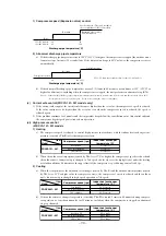
External control (remote display)/control of input signal
1) External control (remote display) output
Following output connectors (CnT) are provided on the control circuit board of indoor unit.
¡
Operation output: Power to engage DC 12V relay (provided by the customer) is outputted during operation.
¡
Heating output: Power to engage DC 12V relay (provided by the customer) is outputted during the heating operation.
¡
Compressor ON output: Power to engage DC 12V relay (provided by the customer) is outputted while the compressor
is operating.
¡
Error output: When any error occurs, the power to engage DC 12V relay (provided by the customer) is outputted.
2) Control of input signal
(Make sure to connect the standard remote control unit. Control of input signal is not available without the standard
remote controller.)
Control of input signal (switch input, timer input) connectors (CnT) are provided on the control circuit board of the
indoor unit.
However, when the operation of air conditioner is under the Center Mode, the remote control by CnT is invalid.
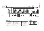
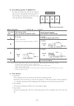
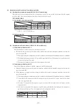
Notes (1) The unit number is set by a switch (SW2) on the circuit board for the indoor unit.
Notes
(2) If unit number is not important, random can be used. However, setting in order from 0, 1, 2, to F will ensure setting without error.
Set SW2 : 0~9, A~F
0
0
1
1
2
2
3
3
4
4
F
F
indoor unit
Remote controller
Outdoor unit
Refrigerant piping
Remote controller wire
Indoor/Outdoor connection wire