


-
111
-
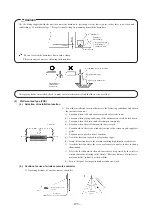
8) Avoid positioning the drain piping outlet at a place where generation of odor may stimulated. Do not lead the drain piping
direct into a sewer from where sulfur gas may generate.
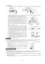
9) Drainage test
a) Conduct a drainage test after completion of the electrical work.
b) During the trial, make sure that drain flows properly through the piping and that no water leaks from connections.
c) In case of a new building, conduct the test before it is furnished with the ceiling.
d) Be sure to conduct this test even when the unit is installed in the heating season.
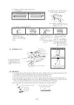
Procedures
1
Supply about 1000 cc of water to the unit through ghe air outlet by using a feed water pump.
2
Check the drain while cooling operation.
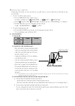
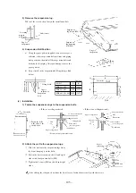
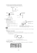
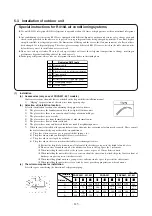
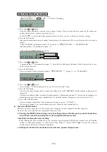
10) Outline of bottom drain piping work
a) If the bottom drain piping can be done with a descending gradient (1/50-1/100), it is possible to connect the pipes as
shown in the drawing below.
b) Do not use acetone-based adhesives to connect to the drain socket.
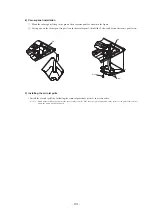
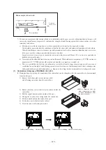
Remove grommet
Make sure to install
it back after test.
Insert water supply hose for
20mm ~ 30mm to suply water.
(Insert hose facing toward bottom.)
Indoor unit
Attached drain hose clamp
Drain pipng
Drain situation can be checked with transparent socket.
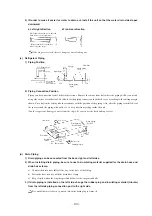
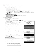
Pour water into a convex joint
If the electrical work has not been completed, connect a convex joint in the drain
pipe connection to provide a water inlet.
Then, check if water leaks from the piping system and that drain flows through
the drain pipe normally.
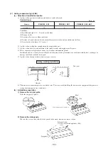
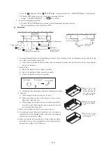
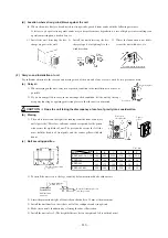
Remove
Drain motor connector
CNR 2P Blue
Connecting port of top drain pipes
Standard hard polyvinyl chloride pipes
Insulating material
Connecting port of bottom drain pipes
Rubber stopper(to be removed)
(Removing drain motor connector) Remove
drain motor connector CNP (blue) as shown
in the drawing on the nght. (Note: If the
connector is left connected, drain water is
discharged from the conncting port of top
pipes, causing leakage.)
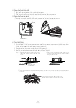
Connection of pipes
Forced drain pump operation
S
Set up from a unit side.
1
Turn power on after selecting the emergency operation mode with a setting on the indoor unit board (SW9-3 ON) and discon-
necting the CnB connector on the board. Then, the drain pump will start a continuous operation 15 seconds later.
(Note: The blower will also start operation in tandem)
2
When a drain test is completed, reinstate the setting to cancel the emergency operation mode (SW9-3 OFF) and plug in the
CnB connector on the board.
(When electrical work is not completed, connect a convex joint to the drain pipe joint area, arrange an inlet and check leaks and
drain connections of the pipe)
S
Setup from a remote controller side.
Drain pump operation from a recomte controller unit is possible. Operate a remote controller unit by following the steps
described below.
1. To start a forced drain pump operation.
1
Press the TEST button for three seconds or longer.
The display will change from “
SELECT ITEM ”
“
SET ”
“
TEST RUN
”