


-
51
-
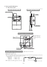
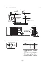
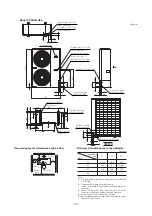
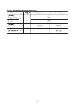
Required space for maintenance and air flow
Minimum allowable space to the obstacles
Unit:mm
Mark
1
2
3
L1
Open
Open
500
L2
300
5
Open
L3
150
300
150
L4
5
5
5
Installation
type
Notes
(1) It is prohibited to install in a space enclosed with walls
at four sides.
(2) Unit must be secured with anchor bolts.
Anchor bolt should not protrude more than 15 mm above
the surface.
(3) Where strong winds blow, the blow outlet must be
oriented at right angle against the wind direction.
(4) Secure a space of 1 m or more above the unit.
(5) Barrier standing in front of the blow outlet must be lower
than the height of unit.
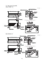
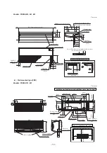
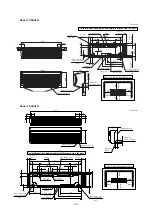
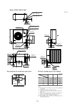
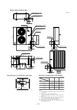
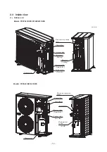
Unit: mm
Model FDCA601HES
VIEW A
L4
L3
L2
L1
60
580
38
50
110
10
46
50
48
100
40
410
15
103
60
50
50
195
50
70
50
15
50
27
50
15
388
262
15
40
55
55
150
1300
40
110
195
589
648
970
200
60
190
20
20
370
A
Air
inlet
Air inlet
Air outlet
Terminal block
Maintenance
space
( )
Liquid piping: ø9.52 (3/8")
(Flare connecting)
Liquid piping: ø9.52 (3/8")
(Flare connecting)
Gas piping: ø15.88 (5/8")
(Flare connecting)
Holes for anchor bolt
(M10
×
4 pcs.)
Opening for electric wring
Opening for electric wring
Opening for electric wring
Opening for piping
and electric wring
Opening for piping
and electric wring
Opening for piping
and electric wring
Opening for piping
and electric wring
Gas piping: ø15.88 (5/8")
(Flare connecting)
Holes for drain
(ø20
×
3 pcs.)