


-
102
-
(2)
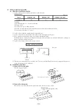
Ceiling suspension type (FDE)
(a)
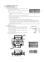
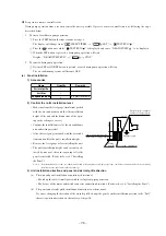
Selection of installation location
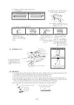
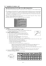
1) A place where good air circulation and delivery can be obtained.
Cold air throw
Models
FDE151, 201
Air throw
7.5
FDE251, 301
8
FDE401, 501, 601
9
Unit : m
Conditions
(1) Installation height: 2.4 ~ 3.0 m above the floor
(2) Fan speed: Hi
(3) Location: Free space without obstacles
(4) Distance of reach indicates the horizontal distance after the wind touched down the floor.
(5) Air velocity at the throw: 0.5 ( m/sec.)
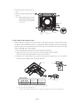
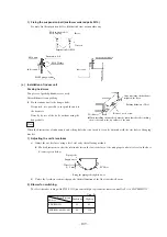
2) A place where ceiling has enough strength to support the unit.
3) A place where there is no obstruction to the return air inlet and supply air outlet ports.
4) Places exposed to oil splashes or steam (e.g. kitchens and machine plants).
Installation and use at such places will incur deteriorations in the performance or corrosion with the heat exchanger or
damage in molded synthetic resin parts.
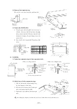
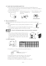
5) A place where the space shown below may be secured.
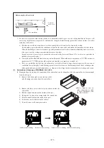
Side panel
Side panel screw
(1 each on the left and right sides) (M4)
6) This unit uses a microcomputer as a control device. Therefore avoid installing the unit near the equipment that generates
strong electromagnetic waves and noise.
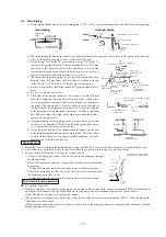
(b)
Installation preparation
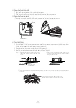
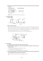
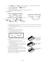
1) Remove the air inlet grille.
Slide the stoppers (4 places).
Unit : mm
5 or more
150 or more
Obstacle
300 or more
100 or more
Ceiling mouting installation
Filter
Pin
Take out the pins (4 or 6 places).
2) Remove the side panels.
Take out the screws, then slide the side panels in the arrow direction to remove them.