4
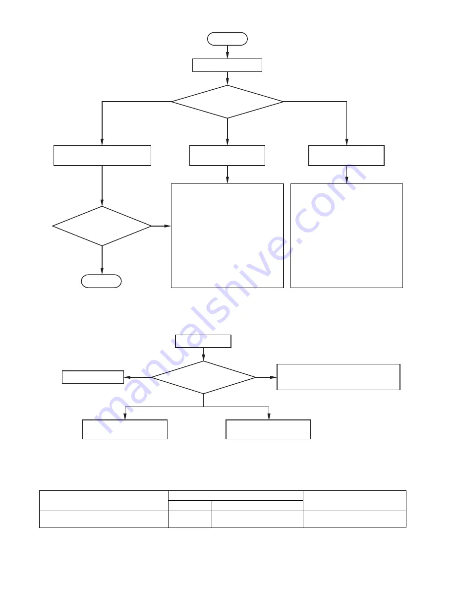
[RS-232C control flowchart]
[Compatibility with the former models]
To use the RS-232C commands designed for the former models of Mitsubishi projector, by inputting “00COMMAND0”,
the projector responds in the same way as the former models. (No NAK is returned.)
(For the recommended procedure to use the former command systems, see “Controlling the projector using a personal
computer” for FL7000U.)
ITEM
Function
Data
Character
ASCII
Changing the RS-232C command system
COMMAND
43h 4Fh 4Dh 4Dh 41h 4Eh 44h 0 (Former command system),
1 (New command system)
0-3
To normal operation
4
6
5
Sending “00vST”
Checking response to “00vST”
Sending out command
OK
NG
END
NAK returned
Command sending fails.
No NAK returned
START
Command is sent successfully.
Command is executed successfully.
Awaiting response
from projector
Command is sent successfully.
Command execution fails.
No response for
1 second or longer
Checking execution of
command (sending out
check command)
Check the following.
•
Check that the function code is correct.
•
Check that the data code is correct.
•
Check that the projector is able to issue
the return command.
Check the projector’s operation using
the 00vST command.
Note: In the following cases, NAK is
returned even when the projector is
in normal condition.
•
Immediately after the power is
turned on (about 20 seconds to 2
minutes)
•
During input switching
•
During auto positioning
•
During password lock
Check the following.
•
Check that the command begins with
“00”.
•
The projector is not supplied with AC
power.
Check that AC power cord is
connected.
Turn on the power. (Turn on the circuit
breaker or main switch.)
•
Not connected with the projector.
Check that the RS-232C cable is
connected.
Check the RS-232C cable for electrical
discontinuity.
Projector error
Send out “00vER” to check error details.
Recover from error state.
Projector is functioning.
Enter password.
Send out “00PASS****.”
[Method of checkin
g
s
tate of projector]
Summary of Contents for XD221U
Page 7: ... 1 2 5 6 OPTICAL UNIT 8 11 14 9 7 10 3 4 12 13 EXPOSED VIEW Fig 1 1 DLP ASSY ...
Page 9: ... Optical unit 2 1 3 4 5 6 7 8 Fig 1 2 ...
Page 11: ... DISASSEMBLY 1 Unscrew the 8 screws a from the bottom cover a a ...
Page 20: ... 17 17 Remove adjuster from the bottom cover Bottom cover Adjuster ...


