- -
DOWNLOAD OF THE FIRMWARE
Outline
Download the firmware to the ROM of the projector by the
program.
Operating conditions
Microsoft® Windows® Me/000/XP shall operate correctly.
(The program doesn’t run on Windows® 9/98.)
A display device supporting VGA (0 x 80) or above is re-
quired.
Necessary files
The following files are necessary to run the program.
• Data folder : Firmware data
Model
Data folder name
XDU/XDU-G
XDv***
(*** indicates the version.)
• [DLP Composer (TM) Lite .]
: Program for download
• [XD_Flash_v***.img] : Firmware data
(*** indicates the version.)
Necessary parts
The following files are necessary for download of the firmware.
○ JIG-DOWNLOAD-FW (859C749O10)
• Jumper
• RSC cable (MD 8P - USB P)
○ AC power cord
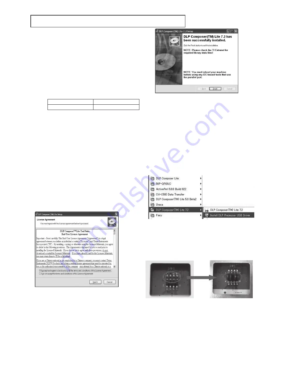
Installing [DLP Composer (TM) Lite]
. Double-click the [DLP Composer Lite v. Setup.exe].
. As installation starts, click [Next] to continue the installation
process.
. On the [License Agreement] screen, move the scroll bar
on the right to the bottom, select [I accept and agree to
be bound by all the terms and conditions of this License
Agreement], and click Next to continue the installation pro-
cess.
4. When the installation is finished, click [Finish] and reboot
the PC. (A shortcut to DLP Composer (TM) Lite is created
on the desktop.)
Preparation before starting the program
. Copy the data folder on the desk-top of the Windows® .
. Disconnect the power cord from the projector.
. After installing the [DLP Composer(TM) Lite .], over-
write the [dlpproc.inf] file in the holder of [C:¥Program
Files¥DLP Composer Lite .] by the attached [dlpproc.inf]
file. And copy the attached [Flash Device Parameter.txt] to
the holder of [C:¥ ProgramFiles¥ DLP Composer Lite .].
. Choose the eye-con of [Install DLP Processor USB Driver]
in the pull down menu of [DLP Composer(TM) Lite .]
which comes out on a program menu. (USB support is in-
stalled.)
. The display of "Press some keys for continuing" should
be comes out to a screen, then press some keys to a key-
board and wait to complete installation.
. Remove the top cover of projector.
. The jump is attached to the parallel port of the connec-
tion terminal of the main board. when update FW process
starts, it doesn’t work if the jump isn’t attached.
Attached the jumps
Summary of Contents for XD221U
Page 7: ... 1 2 5 6 OPTICAL UNIT 8 11 14 9 7 10 3 4 12 13 EXPOSED VIEW Fig 1 1 DLP ASSY ...
Page 9: ... Optical unit 2 1 3 4 5 6 7 8 Fig 1 2 ...
Page 11: ... DISASSEMBLY 1 Unscrew the 8 screws a from the bottom cover a a ...
Page 20: ... 17 17 Remove adjuster from the bottom cover Bottom cover Adjuster ...


