3
SPECIFICATIONS
3.4 Buffer Memory Assignment
3.4.2 Details of the buffer memory
3
- 14
1
OVE
R
VI
EW
2
SYS
TEM
CONFIGURA
T
ION
3
SP
ECIFI
C
A
T
IO
N
S
4
PRO
C
EDURES AND
SETT
ING
S
BEFO
RE
O
PERA
T
IO
N
5
FUNCTIONS
6
UTIL
IT
Y P
A
C
K
A
G
E
(G
X Conf
igu
rat
or-CT)
7
PROGRA
MMING
8
T
R
OUB
L
ES
HO
O
T
ING
(5) Present value A (Un\G10 and 11) and present value B (Un\G200 and 201)
• The present counter value is stored in this area.
• Select the present value A (Un\G10 and 11) to read such as the present value
and overflow detection flag (Un\G12) for each channel, and select the present
value B (Un\G200 and 201) to read the present values of multiple channels at a
time. Set the storage location (present value A/present value B) with the
intelligent function module switch. (Refer to Section 4.5.)
• The range of a value to be read is from -2147483648 to 2147483647 (32-bit
signed binary).
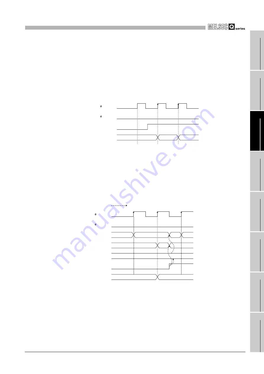
Figure 3.5 Timing chart for the present value A (Un\G10 and 11)
(6) Overflow detection flag (Un\G12)
• Overflow occurrence status is stored in this area when the counter format is the
linear counter (refer to Section 5.2.2).
• According to the overflow occurrence status, 0 (No detection) or 1 (Overflow
occurred) is stored to the overflow detection flag (Un\G12).
• This flag operates as follows. (when the pulse input mode is 1 multiple of 1
phase)
Figure 3.6 Timing chart for the overflow detection flag (Un\G12)
Count enable command
(Y04)
Present value A
(Un\G10 and 11)
ON
2
1
0
A
B
Present value A
(Un\G10 and 11)
Preset command
(Y02)
Overflow detection flag
(Un\G12)
Preset value setting
(Un\G4 and 5)
Error code
(Un\G20)
ON
0
1
0
0
1
0
2147483647
2147483646
100
0
Performed by the QD63P6.
A
B


