3 - 8
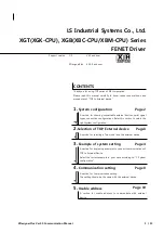
3. SIGNALS AND WIRING
3.1.3 Torque control mode
RA1
RA2
RA3
18
10
SP1
SG
15
5
14
9
8
10
1
11
EMG
SON
RES
RS1
RS2
SG
SD
P15R
LG
12
ALM
19
ZSP
6
VLC
15
5
14
7
16
17
4
LZ
LZR
LA
LAR
LB
LBR
LG
OP
P15R
SD
1
6
CN1B
CN3
13
8
7
SP2
TC
2
VLA
19
RD
RA4
CN1A
3
VDD
COM
9
COM
4
13
3
SD
LG
14
MO1
LG
MO2
CN3
A
A
Speed selection 1
Servo amplifier
CN1A
(Note 4,8)
CN1B
(Note 4)
10m(32ft) max.
(Note 4,8) (Note 4,8)
Plate
(Note 3) Emergency stop
Servo-on
Reset
Forward rotation start
Reverse rotation start
Speed selection 2
Upper limit setting
Analog speed limit
0 to 10V/rated speed
Upper limit setting
Analog torque command
8V/max. torque
(Note 9)
Servo configuration
software
Personal
computer
(Note 7)
Communication cable
2m(6.5ft) max.
Plate
Plate
(Note 7)
Monitor output
Max. 1mA
Reading in both
directions
10k
10k
2m(6.5ft) max.
(Note 4,8)
(Note 1)
Control common
Encoder Z-phase pulse
(open collector)
Encoder Z-phase pulse
(differential line driver)
Encoder A-phase pulse
(differential line driver)
Encoder B-phase pulse
(differential line driver)
(Note 10)
Trouble
Zero speed
Limiting torque
(Note 2,5)
Ready
(Note 6)
(Note 4,8)
(Note 11)
Summary of Contents for MR-J2S-*A series
Page 37: ...1 18 1 FUNCTIONS AND CONFIGURATION MEMO ...
Page 139: ...5 34 5 PARAMETERS MEMO ...
Page 167: ...7 12 7 GENERAL GAIN ADJUSTMENT MEMO ...
Page 177: ...8 10 8 SPECIAL ADJUSTMENT FUNCTIONS MEMO ...
Page 179: ...9 2 9 INSPECTION MEMO ...
Page 199: ...11 8 11 OUTLINE DIMENSION DRAWINGS MEMO ...
Page 207: ...12 8 12 CHARACTERISTICS MEMO ...
Page 273: ...14 28 14 COMMUNICATION FUNCTIONS MEMO ...
Page 339: ...15 66 15 ABSOLUTE POSITION DETECTION SYSTEM MEMO ...